•
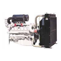
Install a guide bar into a bolt hole on the
crank shaft, and lift the flywheel to align
the dowel pin with the pin hole on the fly-
wheel for temporary assembly
operation.
•
Coat the adhesive (#271 Loctite) over
the assembling bolts and install bolts in
the remaining holes. After that take out
the guide bar, then install a bolt in the
hole where the guide bar had been
inserted.
•
According to the order of tightening
tighten the fixing bolts using a torque
wrench in a diagonal sequence to speci-
fied torque.
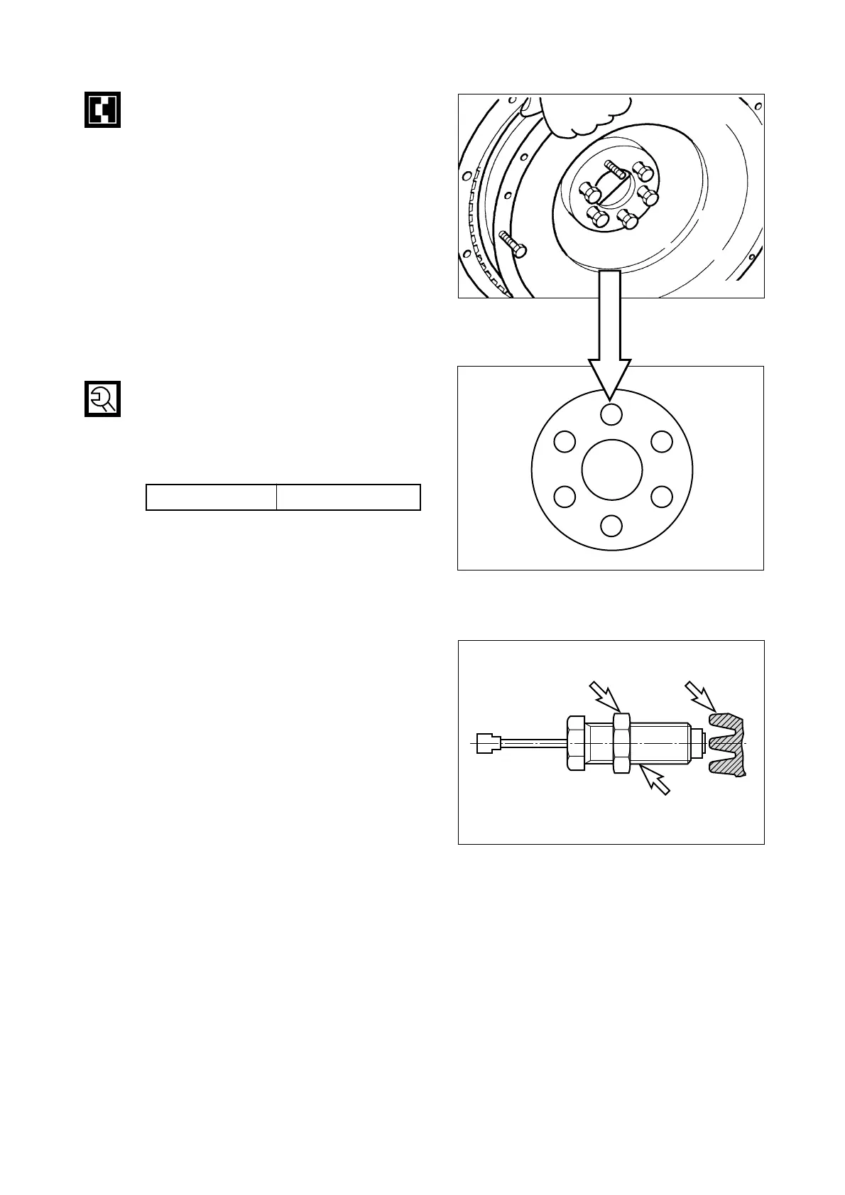
9.3.9. Tacho sensor (Pick-up sensor)
•
Move the lock nut to hexagonal side of
sensor completely.
•
Rotate (CW) the tacho sensor on fly
wheel housing, until the end of it reach
on fly wheel ring gear.
•
Rotate (CCW) the tacho sensor for 270
˚
(gap 1.0 mm) and fix lock nut.
•
Tolerance limit is 27
˚
. (gap
±
0.1 mm)
9.3.10. Water chamber cover
•
Coat the adhesive over the water cham-
ber cover (Particular around bolt holes)
and after attaching the gasket, assemble
it to the cylinder block using the bolts for
assembling.
•
As for tightening of bolts, after primarily
tightening the bolts located at the both
ends of cover (4ea at both sides) and
middle bolts (Upper, lower 2ea) , tighten
the rest.
- 102 -
 Loading...