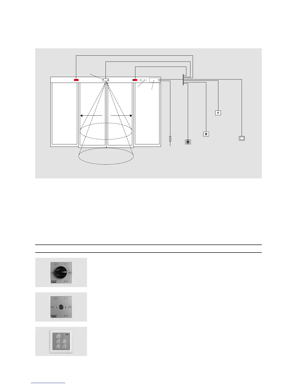
PROGRAM SWITCHES
—
A program switch from DORMA's
broad range of accessories
allows the automatic door
system to meet individual
requirements and provides easy
handling.
The corresponding 3-position
program switches are available
in various designs and suitable
for all kinds of applications.
They offer various options, from
a mechanical to a full-electronic
version, alternatively also
lockable via profile half-cylinder
or in a full-electronic way via
code..
.
Up to 5 different functions:
Off, Automatic, Exit Only,
Partial Open, Permanent Open
.
Electronic program switches
in System 55 design to
meet the highest aesthetical
demands
For sliding door operators Designation Specification Installation system Order No.
PG-S1 5-position, aluminium, white,
flush-mounted version, 80 x 80 x 40 mm Gira S-Color 19135401150
PG-S2 5-position, lockable, aluminium, white,
flush-mounted version, 80 x 80 x 40 mm Gira S-Color 19135602150
EPS-S Full-electronic program switch in
System 55 design, 5-position, lockable via code
or additional TL-ST S55 key switch,
membrane keypad aluminium-coloured, white,
flush-mounted version, 80 x 80 mm System 55 16556901150