8
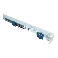
1 LM-Träger 200 mm
2 ES 200 Antriebsprofil
3 Kabelkanal U-Form
4 Scharnierprofil
5 Innenverkleidung 200 mm
6 Laufprofil mit Dämmlage
7 Abdeckprofil für LS-Kabel
8 U-Profil
5
3
2
4
1
6
7
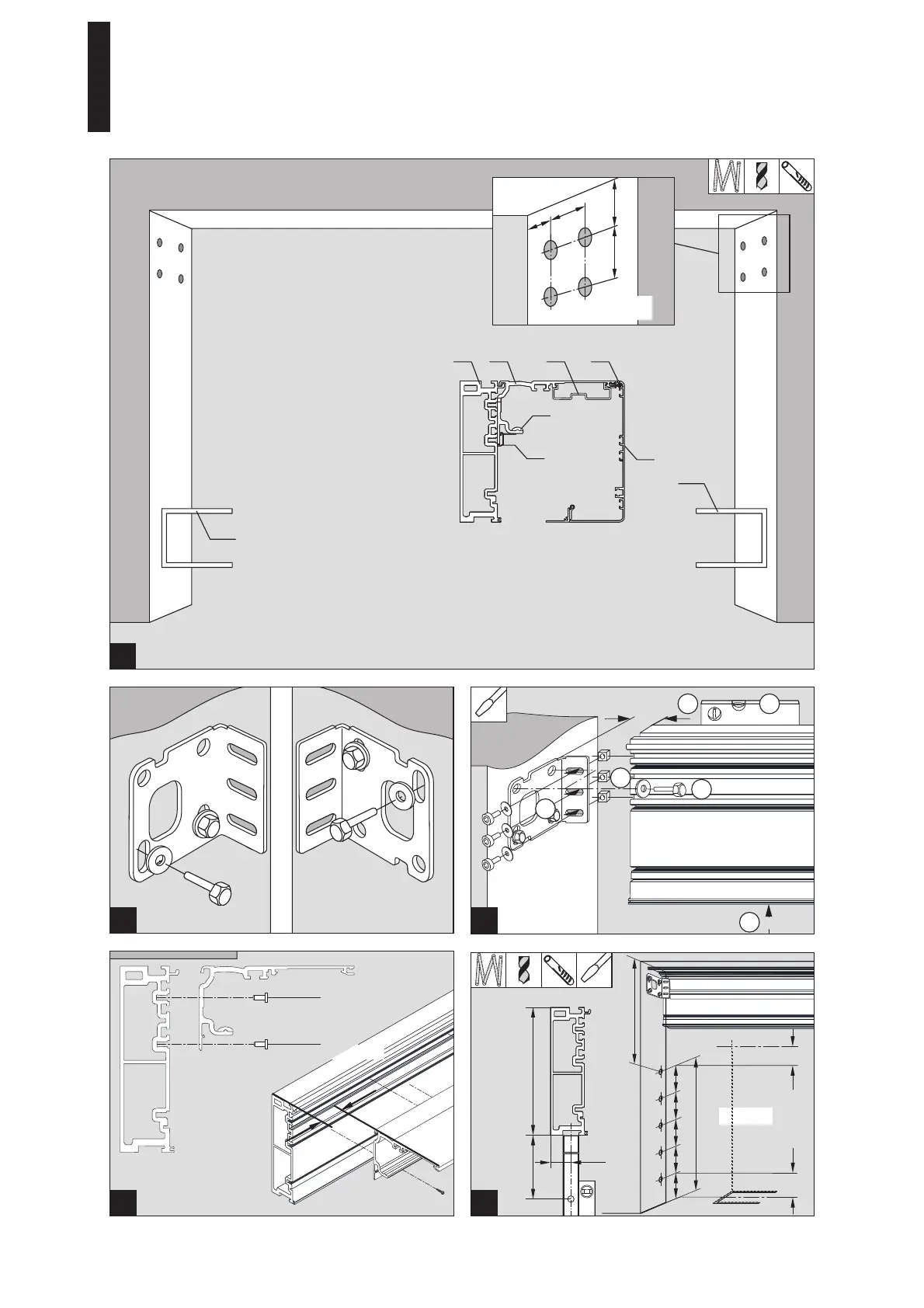
1 Aluminum girder 200 mm
2 ES 200 operator profile
3 U-section cable trunking
4 Hinge profile
5 Internal cover 200 mm
6 Rail track profile with rubber strip
7 Cover profile for rail track cable
8 Channel section
8
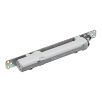
55
42
min 50
78
LH + 128 (LM = 200)
12 mm
M6 x 20
DIN EN ISO 10642
XX
X = min. 40
M6 x 16
DIN EN ISO 10642
300
OKFOKF
4 x n
100
100
1
2
4
3
5
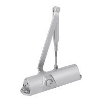
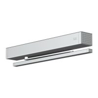
3. Montage LM-Träger / Mounting instruction of aluminum girder
Wichtiger Hinweis / Important remark
Ab einer LM-Träger-Länge von
4.200 mm wird empfohlen, den
Träger/das Antriebsprofil im Bereich
der HSK und bei Bedarf zusätzlich im
Bereich der NSK am Baukörper nach
oben abzufangen / For an aluminum
girder length of 4,200 mm or more it
is recommended to additionally
mount the girder/operator profile
upwards to the building structure
close to the HSK and if necessary
also close to the NSK.
9DORMA
SST FLEX ES 200
—