Do you have a question about the Dorma TS93 Series and is the answer not in the manual?
Determine door hand, deadstop, and prepare frame/door for fasteners per template.
Attach mounting plate to the frame using the lower four holes, ensuring arrows point up.
Mount the closer onto the previously installed mounting plate.
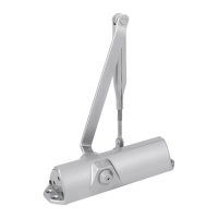
Connect the closer arm to the pinion, ensuring it is parallel to the door.
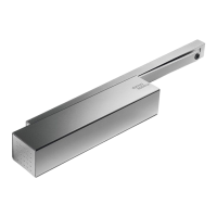
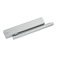
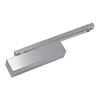
Insert shoe/blocks into track, attach track to door using mounting screws.
Align arm hole with slide shoe in track, insert screw, tighten, and install track cover.
Adjust sweep, latch, backcheck, and delayed action valves for optimal performance.
Instructions for adjusting hold-open position, force, and engagement/disengagement.
Adjust spring tension as required, particularly for barrier-free openings, following charts.
Slide end covers over closer body end caps and secure the cover with a locking screw.
| Backcheck | Adjustable |
|---|---|
| Delayed action | Adjustable |
| Certification | EN 1154 |
| Closing Speed | Adjustable |
| Latching Action | Adjustable |
| Opening angle | Up to 180° |
| Temperature range | -15°C to +40°C |
| Type | Cam action door closer |
| Mounting | Surface mounted |
| Hold-open | Optional |
| Cover | Metal |
| Application | Suitable for single and double leaf doors |
| Finish | Silver |
| Max. Door Width | 1250 mm |