TS 99 FL EN 2-5
—
2
Mounting instructions
2. Transom mounting on the push side
2.1 Drill fixing points for closer and slide channel as per
template.
Lay 24 V DC power supply cable from the central
smoke detector.
2.2 Fix mounting backplate.
2.3 Fix closer to the mounting backplate.
2.4 Connect the internal cable to the connector of the
electro-hydraulic hold-open device.
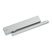
2.5 Attach, align and firmly fix slide channel.
2.6 Open door c. 45° À, place lever approx 10° to closer Á
and bolt on Â.
2.7 Close valve to regulate closing speed À, push lever in
direction of slide channel Á and connect lever with
nylon slider Â.
2.8 Adjust spring strength (closing force).
2.9 Adjust closing speed 180° – 0° À.
Adjust latching action 7° – 0° Á.
2.10 Setting the free-swing function
Switch on power (24 V DC).
Open the door leaf to the required hold-open
position Á. The closer spindle is held in this position
by the electro-hydraulic hold-open device, but the
door can be freely moved thanks to the free-swing arm
assembly. Leave the door open.
2.11 Functional test
Interrupt power supply using manual pushbutton (e.g.
DORMA HT) À. The hold-open device is de-energised
and the door is closed Á.
Ensure that the cables are not damaged in this
process.
2.12 Clip on end caps À.
Break out the tab as marked for the spindle recess in
the cover Á. Clip on cover Â.
Clip on DORMA logo badge Ã.
Clip on slide channel cover Ä.
2.13 Place door stop (not included in standard equipment)
to prevent door leaf and level from touching.
3. Technical Data
Operating voltage: 24 V DC ±15%
Power consumption: approx. 2 W
Duty factor: 100% continuous duty
Activation is effected via an external central smoke detector
with integral power pack (e.g. DORMA RMZ).
4. Final inspection and maintenance
Instruction sheet relating to the use and application of
hold-open systems.
1)
EN 14600 Appendix C.
Further information / regulations
Guidelines for hold-open systems published by
the Institute for Building Technology, Berlin
1)
, or
equivalent national guidelines.
1)
These documents are only printed in German as they refer exclusively to the
German market.
Subject to change without notice
EN
According to the guidelines for hold-open systems
issued by the Institute for Building Technology, Berlin,
it must be possible to release every hold-open device
by manual means.
If free-swing door closers are used, release must be
initiated by a pushbutton.
The manual release pushbutton used for this must
be red and carry the inscription “Close Door”. The
pushbutton must be in the immediate vicinity of the
door (barrier) and must not be concealed when the
door (barrier) is open.
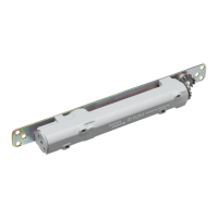
The DORMA TS 99 FL is non-handed.
The following relates to installation for an LH (ISO 6)
door. In the case of RH (ISO 5) doors, apply mirrored
arrangements as applicable.
1. Door leaf mounting on the pull side
1.1 Drill fixing points for closer and slide channel as per
template.
Lay 24 V DC power supply cable from the central
smoke detector.
1.2 Fix junction box.
1.3 Fix mounting backplate.
1.4 Fix closer to the mounting backplate.
Ensure that the cable is located in the mounting
backplate groove and that it remains undamaged.
1.5 Connect power supply cable (24 V DC from the central
smoke detector) to the junction box terminals À.
Connect interconnecting cable Á.
Connect the internal cable to the connector of the
electro-hydraulic hold-open device Â.
1.6 Fit arm at an angle of approx. 10° from the door leaf
and tighten fixing screw.
1.7 Attach, align and firmly fix slide channel.
1.8 Close valve for adjusting closing speed À, and open
door approx. 45° Á.
1.9 Push arm towards slide channel À and connect to
slide block Á.
1.10 Adjust spring strength (closing force).
1.11 Adjust closing speed 180° – 0° À.
Adjust latching action 7° – 0° Á.
1.12 Setting the free-swing function
Switch on power (24 V DC) and set junction box
switch to “ON” À.
Open the door leaf to the required hold-open
position Á. The closer spindle is held in this position
by the electro-hydraulic hold-open device, but the
door can be freely moved thanks to the free-swing arm
assembly. Leave the door open.
1.13 Functional test
Interrupt power supply using manual pushbutton (e.g.
DORMA HT) À. The hold-open device is de-energized
and the door is closed Á.
Ensure that the cables are not damaged in this
process.
1.14 Clip on end caps À.
Break out the tab as marked for the spindle recess in
the cover Á. Clip on cover Â.
Clip on DORMA logo badge Ã.
Clip on slide channel cover Ä.
 Loading...