4
installation details (continued)
Supply Trigger Wiring
Trigger Signal Wiring Notes
• If one or more product signals are not used, they do not need to be connected.
• If you are triggering more than one product from a single signal, connect all of the Machine Interface signal wires for those
products to that signal.
• Protect any unused wire with a wire nut or an insulated connector. If the washer has only a single common, connect all the
common wires together.
• One of the 6 LEDs on the Machine Interface will light up when the corresponding valid signal is received.
Supply Trigger Wiring by Operation Mode
Connect by Operating Mode to:
Trigger Supply Signal Signal Common Standard Pump Mapping
Signal 1
Black Wire White & Black Wire
Product 1
Prewash
Signal 2 Brown Wire White & Brown Wire Product 2 AFS
Signal 3 Red Wire White & Red Wire Product 3 Mainwash (2H/2C)
Signal 4 Orange Wire White & Orange Wire Product 4 Mainwash (2H/2C)
Signal 5 Yellow Wire White & Yellow Wire Product 5 Spare
Signal 6
Blue Wire White & Blue Wire
Product 6
Final Rinse
Cellular Gateway Installation
One cellular gateway is needed for up to four Connected Total Eclipse controllers, for real-time connectivity. To install the
cellular gateway follow the steps below:
1) Using a cellular signal strength indicator or the powered gateway (120 or 240 VAC depending on the model) determine
a suitable mounting location for the gateway that is close to the washers and dispensers (standard cable length is 50
feet or 15 meters, but this cable can be as long as 400 feet or 125 meters) and has adequate cellular signal. Hydro’s
recommendation is that the gateway have a good or excellent connection to minimize outages or data loss (see LED table
on next page).
2) The gateway can be physically mounted using either the included DIN Rail kit or a third-party enclosure (not included).
DIN Rail: The aluminum DIN-rail attachment plate is already attached to the product’s casing. To mount the UC-8100A-ME-T
on to a DIN rail, make sure that the stiff metal spring is facing upwards and follow these steps.
a) Pull down the bottom slider of the DIN-rail bracket located at the back of the unit.
b) Insert the top of the DIN rail into the slot just below the upper hook of the DIN-rail bracket.
c) Latch the unit firmly on to the DIN rail.
d) Push the slider back into place.
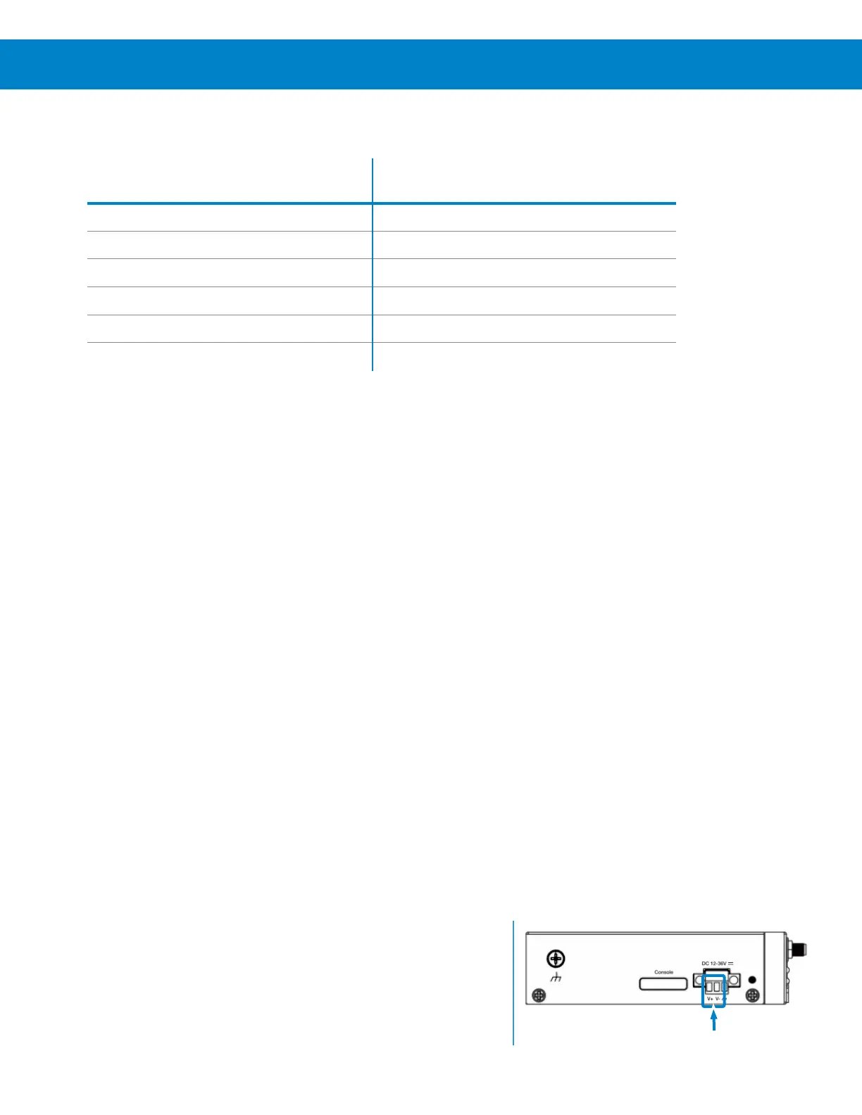
Power Connections
3) Connect the power jack (included in the gateway package) to the
gateway’s DC Power Input terminal block using the crimp connectors.
a) Connect the white dashed wire on the power jack to the V+ terminal.
b) Connect the black wire on the power jack to the V- terminal.