5
installation details (continued)
Cellular Gateway Installation (continued)
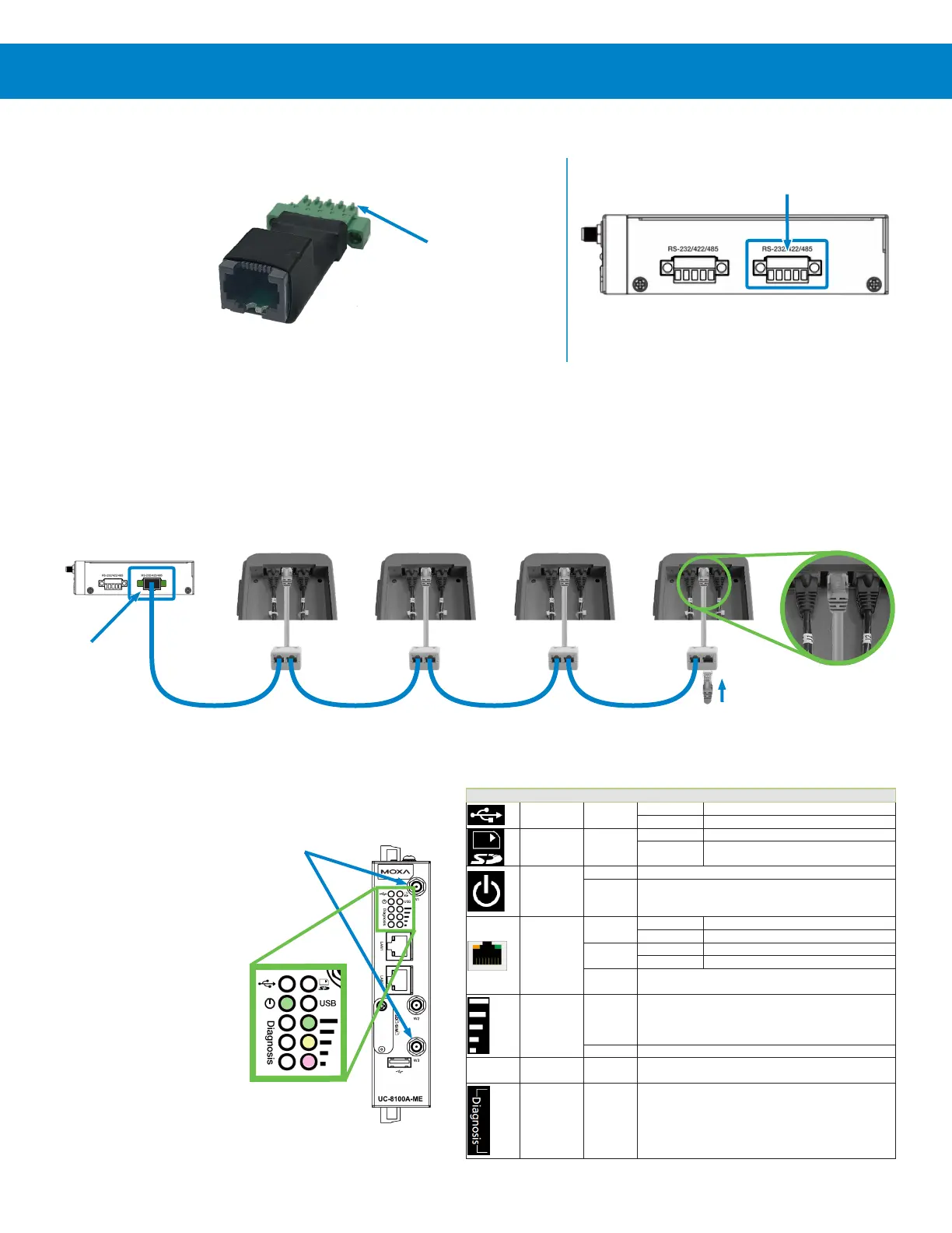
4) Connect the interface board (included in the gateway package) to the
Serial Port 2.
This RS485 interface board may be installed on up to four Connected
TE controllers to establish communications with the gateway.
5) Using the provided interface cables (1 per Connected TE), daisy chain each cable splitter and Connected TE together, as
shown below.
The splitter closest to the gateway would be connected to the RS485 interface board via the long interface cable (provided
with the gateway).
The splitter furthest from the gateway should have its open port plugged with the provided terminator.
6) Install the two Cellular
Antennas by screwing
them onto the
threaded ports W1
and W3 as indicated.
7) With everything
connected, ensure
that the Power LED
illuminates green
(see table to right)
and wireless signal
strength LEDs are
denoting Good or
Excellent.
Gateway
Controller 1
/ Node 1
Controller 2
/ Node 2
Controller 3
/ Node 3
Controller 4
/ Node 4
Plug Splitter
into center
port
RS485
Interface
Board
RS485
Interface
Board
Serial Port
Connection Pins
Cellular
Antenna
Connections
Serial Port 2
Terminator
LED Name Color Function
USB Green
Steady On USB device is connected and working normally.
Off USB device is not connected.
SD Green
Steady On SD Card inserted and working normally.
Off SD card is not detected.
Power
Green Power is on and the computer is working normally.
Off
Power is off.
LAN1/
LAN 2
(RJ45
connector)
Green
Steady On 100 Mbps Ethernet link
Blinking Data transmission in progress
Yellow
Blinking Data transmission in progress
Off
Ethernet is not connected.
Wireless Signal
Strength
Green
Yellow
Red
The number of glowing LEDs indicates the signal strength.
3 (Green + Yellow + Red): Excellent
2 (Yellow + Red): Good
1 (Red): Poor
Off Wireless module is not detected.
USR User-defined Green
This LED can be defined by users. For details, refer to Hardware
User’s Manual.
Programmable
diagnostic LEDs
Green
Yellow
Red
These three LEDs are programmable. For details, refer to the
“Default Programmable Button Operation" section in the Hardware
User’s Manual.