contact us at www.DRpower.com 13
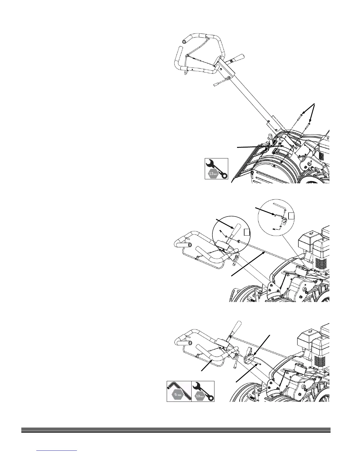
Operation Handle
1. The M8×75 bolts and nuts have been fixed in the guide
bracket for shipping. First, remove the M8x75 bolts and
nuts from the guide bracket.
2. Align the holes in the operation handle shaft with the
holes in the guide bracket and re-insert the M8x75 bolts
and screw nuts to tighten. (See Figure 5)
Shift Lever
1. Insert lower end of shift rod into hole of shift lever
indicator. Fasten with bridge clip and washer. (see Figure
6, Illustration 1)
2. Insert the upper end of shift rod into hole of shift lever.
Fasten with bridge clip and washer. (see Figure 6,
Illustration 2)
Throttle Control
1. The M6×50 screw and nut have been fixed in the throttle
for shipping. First, remove the M6×50 screw and nut from
the throttle.
2. Then, align the hole in throttle control and the hole in the
upper handle. (See Figure 7) Insert the M6×50 screw and
screw the nut to tighten. Pay attention to the degree of
tightness, and make sure the throttle lever can be moved
normally.
 Loading...