12 DR
®
TRIMMER/MOWER
™
Assembly & Operating Instructions
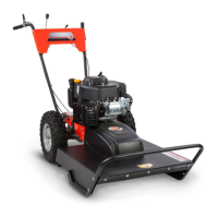
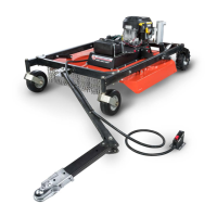
The height of the handlebar depends on many
factors for each individual. However, it is
crucial to find a height that allows the Mow-
Ball
™
Support to glide along the ground and
remain balanced without the operator having to
push down or pull up on the handlebars. At the
proper height, your hands should rest at a
comfortable level and the front end should roll
easily on the Mow-Ball
™
Support.
To adjust the height of the handlebars, loosen the
lock nuts on the U-bolts. Push the handlebars
forward for more height, backward for less.
Then tighten the nuts securely.
Step 6: Install the Parallel Trimming Action (PTA
™
) Lever
1. Insert the straight end of the L-shaped PTA
™
lever through the hole in the center of the
lower handlebar (Figure 11).
2. Align the flat end of the PTA
™
lever with the
corresponding hole in the PTA
™
latch installed
at the center rear of the frame (Figure 12).
3. Mount a 5/8" long bolt through the two holes.
Tighten with a lock nut until there is slight
resistance, then back off two full turns.
Note: If the lock nut is too tight, the PTA
™
lever will be hard to engage.
4. Install the black, vinyl PTA
™
lever handle grip
over the operator's end of the lever (Figure
11).
Step 7: Attach the Acrylic Engine Shield
Use the four remaining sets of 5/8" long bolts and
lock nuts to attach the acrylic engine shield.
We have found it's easiest to tip the machine back
on its handlebars in order to reach the underside.
1. Position the shield on the frame in front of the
engine with the bend at the top facing the
handlebars (Figure 13).
2. Insert the bolts from the outside facing in,
screw on the nuts and tighten (Figure 13).
Figure 11
Figure 12
Figure 13