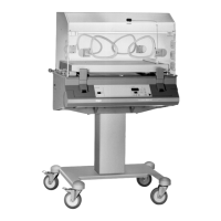
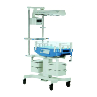
6141.22X Incubator 8000 IC/SC/NC
Function Description
09.99 Page 42 of 49
f. storage battery switching circuit
During operation the storage battery is connected to a charging circuit consisting of R6 to R9
and transistor V23.
3.2.8 Motherboard PCB
3.2.8.1 Intended use
The Motherboard PCB interconnects all PCBs of Incubator 8000 series. Moreover, the
components for the digital signal processing (except CPU) are installed on this PCB.
3.2.8.2 Detailed description of function blocks
a. address decoder
b. PIA
c. over-temperature alarm
d. fan failure alarm
e. watchdogs
f. +5 V voltage monitoring
g. indication air heating
h. monoflop for INOP-LED
i. triggering of additional fan
a. address decoder
Via the address decoders D4 and D5 the CS-signals from the address range 8XXXh are
generated.
b. PIA
PIA D1 is addressed via the addresses 8010h to 8013h, PIA D2 via addresses 8020h to
8023h.
Assignment of PIA Ports D1 (E = input, A = output)
Port Function
PA0 E Indication over-temperature
PA1 E Code skin temperature
PA2 E Code 02
PA3 A Addressing of Multiplexer (A0)
 Loading...