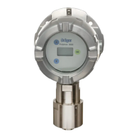
What to do if Dräger Polytron 8200 datalogger in Stack mode is 90% full?
- WWalter LeeAug 20, 2025
If the datalogger in Stack mode is 90 % full, read out the data as soon as possible, clear the datalogger and start again.
What to do if Dräger Polytron 8200 datalogger in Stack mode is 90% full?
If the datalogger in Stack mode is 90 % full, read out the data as soon as possible, clear the datalogger and start again.
What to do if Dräger Polytron 8200 datalogger in Stack mode is 100% full?
If the datalogger in Stack mode is 100 % full and is not logging any more data, read out the data, clear the datalogger and start again.
What to do if Dräger Polytron 8200 shows 'Calibration interval expired'?
If the calibration interval has expired, recalibrate the device.
What to do if Dräger Polytron 8200 shows 'Faulty zero-point'?
If a faulty zero-point is indicated, perform zero-point calibration.
What to do if Dräger Polytron 8200 alarms are disabled?
If alarms are disabled, enable alarms.
What to do if Dräger Accessories performs faulty span calibration?
If a faulty span calibration was performed, perform a new span calibration.
What to do if Dräger Accessories displays 'No valid date or time set'?
If no valid date or time is set, set the time and date.
What to do if Dräger Accessories SW dongle has been removed without logging out?
If the SW dongle has been removed without logging out, disable the SW dongle.
What to do if Dräger Polytron 8200 Accessories is not detecting any sensor?
If the device is not detecting any sensor, check the contacts.
What to do if Dräger Polytron 8200 displays 'Battery almost used up'?
If the battery is almost used up, have the device checked by DrägerService®.
Outlines essential safety precautions and user responsibilities for operating the device.
Explains the meaning of warning, caution, and notice icons used throughout the manual.
Illustrates the components of the explosion-proof device without the e-Box.
Illustrates the components of the explosion-proof device with the e-Box.
Explains the heat of combustion principle used by the DD/LC sensor.
Explains the infrared absorption principle used by the IR sensor.
Lists substances that can impair sensor sensitivity and require re-calibration.
Defines the device's purpose, application areas, and connectivity options.
Step-by-step instructions for connecting power and signal cables.
Instructions for wiring the device when the optional relay module is fitted.
Guidance on connecting the device to external control systems.
Information on connecting the device to a PC for data transfer or configuration.
Overview of the PC software for device management and data analysis.
Instructions for installing various software dongles to enable specific functions.
Explains how to navigate the device's menu structure using the magnetic wand or buttons.
Details the process for adjusting settings and parameters within the menu.
Describes how to exit menu screens and return to measurement mode.
Lists and explains special symbols that appear on the device display.
Describes the meaning of the device's LED indicators (red, yellow, green).
Guides on how to access and view device information without making changes.
Explains how to access a simplified menu for quick status checks.
Details the procedure for accessing the main configuration menu via password.
Describes the normal operating state where the device displays gas concentration.
Explains the 4-20 mA output signal and its relation to gas concentration.
Step-by-step guide for performing a zero-point calibration.
Step-by-step guide for performing a span calibration using test gas.
How to view active warning messages in plain text.
How to view active fault messages in plain text.
How to view fault/warning codes in a numerical table.
Shows a list of installed hardware modules.
Displays the date of the most recent calibration.
Displays the date when the next calibration is due.
Shows whether the datalogger is active or inactive.
Visualizes sensor measurements over a 15-minute period.
Protects device configuration from unauthorized changes using a password.
Configures alarm outputs via relays and LEDs.
Explains the functional relationship between latching and acknowledgement settings for alarms.
Simulates the A1 alarm status for testing purposes.
Simulates the A2 alarm status for testing purposes.
Simulates the fault status for testing the fault relay and LED.
Sets or changes passwords for calibration and settings menus.
Configures the device's internal clock for accurate logging and operation.
Selects the user interface language for the device display.
Assigns a specific function to the device's function key.
Restores all device parameters to their default factory values.
Disables installed software dongles before removal or in case of faults.
Configures display contrast, mode, and enables a display test.
Configures HART interface parameters like polling address and unique identifier.
Displays Unique ID and configures measuring point name (tag).
Guides on selecting Dräger REGARD protocols for communication.
Configures analog interface settings for fault, warning, and maintenance signals.
Explains signal types and sets current values for various analog interface states.
Describes testing functions for fault, warning, and maintenance signals on the analog interface.
Notes Profibus address is not yet active for future use.
Enables/disables auto calibration and selects the specific sensor type.
Configures gas type, measuring range, and units for gas detection.
Resets sensor to factory settings and defines the calibration interval.
Configures datalogger trigger function, threshold, and storage mode.
Enables/disables the datalogger and configures the sampling interval.
Selects peak/average storage and clears datalogger data.
Specifies recommended intervals for device inspection and maintenance.
Step-by-step guide for safely replacing the device's sensor.
Step-by-step guide for safely replacing the device's main electronics board.
Details analog output current, drift, and fault/maintenance signal specifications.
Specifies operating voltage range, inrush current, and maximum operating currents.
Provides housing specifications like protection class and dimensions.
Lists specifications for pressure, humidity, and temperature for sensor operation.
Provides torque values and cable size requirements for installation and wiring.
Lists default settings for various alterable parameters of the Polytron 8200/8310.
Lists available models of the Dräger Polytron 8200/8310 gas detector.
Lists sensing heads compatible with remote sensor configurations.
Lists common replacement sensors for direct installation.
Lists various accessories available for the Polytron 8200/8310 and its sensors.
Lists available replacement parts for the device and its components.
| Product Type | Gas Detector |
|---|---|
| Category | Accessories |
| Type | Fixed Gas Detector |
| Housing Material | Stainless Steel or Aluminum |
| Detection Principle | Catalytic |
| Output | 4-20 mA, HART |
| Protection Rating | IP66 |
| Operating Temperature | -40 °C to +65 °C (depending on sensor) |

