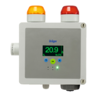
Do you have a question about the Dräger PointGard 2200 CAT and is the answer not in the manual?
Essential safety instructions and compliance requirements for using the product.
Connect power, wait for warm-up, calibrate, and test.
Display, LEDs, symbols, and control panel functions.
Test gases, preparation, zero, and span calibration.
Replacing fuses and resolving common fault messages.
Addressing warning messages and their causes.
Performing bump tests and creating maintenance schedules.
Replacing sensors and testing the display.
Setting up alarms and testing connected devices.
Setting up analog output parameters for control units.
Testing analog signals and configuring beam block functionality.
Measuring ranges, signal transmission, and power supply.
| Type | Fixed gas detector |
|---|---|
| Response Time | T90 ≤ 15 s (typical, depending on sensor and gas) |
| Operating Temperature | -40 °C to +65 °C (depending on sensor) |
| Power Supply | 19 to 30 VDC |
| Certifications | ATEX, IECEx, UL, CSA (depending on configuration) |
| Target Gas | Carbon Monoxide (CO), Hydrogen Sulfide (H2S), Oxygen (O2), Combustible Gases (LEL) |
| Sensor Type | Electrochemical, Catalytic |
| Detection Principle | Electrochemical, Catalytic Bead, Infrared Absorption |
| Detected Gases | Carbon Monoxide, Hydrogen Sulfide, Oxygen |
| Output Signal | 4 to 20 mA |
| Enclosure | Stainless steel |
| Battery Life | N/A (fixed gas detector) |
| Weight | Approx. 1.5 kg |
| Protection Rating | IP66 |
| Humidity | 10 to 95 % RH, non-condensing |
| Operating Humidity | 10 to 95 % RH, non-condensing |
