Do you have a question about the Dräger PointGard 2100 EC and is the answer not in the manual?
Essential safety precautions and user responsibilities for product operation.
Defines the permissible operating environments and limitations.
Guidelines for physical placement and mounting of the instrument.
Requirements for connecting the instrument to electrical power sources.
Explanation of warning symbols and their significance in the manual.
Defines text formatting and symbols used throughout the document.
Lists registered trademarks associated with the product and its components.
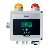
Identifies components and features shown in diagrams and illustrations.
Details the various functionalities and specifications of the Dräger PointGard 2000 instruments.
Procedure for safely accessing and securing the instrument's housing.
Information on connecting the power supply, including wiring diagrams.
Step-by-step guide for attaching the power cable to the instrument.
Instructions for physically attaching the instrument to a surface or bracket.
Details on connecting external devices via analog and relay interfaces.
Guidance on integrating the instrument with Dräger control systems.
Procedure for installing optional software dongles for enhanced functionality.
Procedure for installing an electrochemical (EC) sensor into the instrument.
Instructions for connecting and installing remote sensing head units.
Steps to take after installation to prepare the instrument for operation.
Overview of the instrument's display, analog output, and relay status indicators.
Explanation of the meaning of the instrument's LEDs and status symbols.
Detailed meanings of various symbols shown on the instrument's display.
Description of the buttons and their functions on the instrument's control panel.
Accessing and navigating instrument information and using the function key.
Overview of the instrument's menu structure and navigation.
Information on the types of test gases used for calibration and their properties.
Steps and prerequisites for preparing the instrument for calibration.
Detailed instructions for setting up the calibration equipment and process.
Specifies the correct gas flow rates required for different sensor calibrations.
Procedure for calibrating the sensor's zero point using ambient air or calibration gas.
Procedure for calibrating the sensor's span using a calibration gas of known concentration.
Step-by-step guide to executing a span calibration for specific sensor types.
Reference to automatic calibration procedures in the technical manual.
Instructions for safely replacing a blown fuse in the instrument.
List of common fault codes, their causes, and recommended remedies.
List of warning messages, their causes, and recommended actions.
Procedure to verify alarm activation without triggering actual alarms.
Guidance on establishing a preventive maintenance schedule for the system.
Detailed steps for replacing a sensor, including pre-checks and post-replacement procedures.
Procedure for setting or changing access passwords for calibration and configuration.
Instructions for configuring the instrument's internal date and time settings.
How to select the desired language for the instrument's interface.
Customizing the functionality assigned to the instrument's function key.
Procedure to restore the instrument to its original factory default configurations.
Overview of how latching and non-latching relays interact with alarms.
Configuration options for the instrument's alarm and fault relays.
Settings for configuring alarm thresholds, directions, and latching behavior.
How to test the functionality of alarms, relays, and LEDs.
Procedure for safely deactivating software dongles.
Options for customizing the instrument's display appearance, like backlight and contrast.
Configuration of integrated alarm device patterns using DIP switch settings.
Configuration of the analog output for transmitting measured values to a control unit.
Adjusting the analog output offset for precise 4mA point calibration.
Adjusting the analog output span for precise 20mA point calibration.
Procedures for testing the analog interface by simulating output signals.
Configuration of the beam block function for IR sensors to detect dirty optics.
Enabling or disabling the automatic sensor calibration feature.
Configuring the range to filter out minor measurement fluctuations.
Restoring sensor settings to their factory default values.
Defining the frequency for sensor calibration reminders.
Enabling a feature to prevent unauthorized sensor changes.
Managing software dongles, including deactivation.
Specific settings for the PointGard 2100 EC sensor.
Configuring gas type, measuring range, and units for EC sensors.
Specific settings for the PointGard 2200 CAT sensor.
Specific settings for the PointGard 27x0 IR sensor.
Overview of adjustable settings and their default values within the instrument menu.
Default configurations for various sensor types, including alarm levels and ranges.
Default settings for PointGard 2200 CAT with DrägerSensor® LC.
Default settings for PointGard 2200 CAT Remote DSIR.
Default settings for the PointGard 2700 IR instrument.
Default settings for the PointGard 2720 IR instrument.
Guidelines for safe and environmentally responsible disposal of the product.
Safety warnings and instructions for the disposal of electrochemical sensors.
Specifies the measurement ranges for different sensor types used with the instrument.
Details on the analog signal output and its behavior in various operating modes.
Technical specifications for the AC and DC power supply requirements.
Information on the instrument's physical dimensions, weight, and enclosure.
Operating and storage conditions, including temperature and humidity limits.
Recommended torque values for various threaded connections on the instrument.
Guidelines for selecting and installing cables for CatEx remote sensors.
Guidelines for selecting and installing cables for PIR remote sensors.
Default alarm thresholds and measurement ranges for various sensor types.
Default alarm thresholds and measurement ranges for EC sensors.
Overview of accessories and spare parts for the PointGard 2xx0 series.
Specifications for screws used for mounting the instrument.
List of accessories and parts specific to the PointGard 2100 EC model.
List of accessories and parts specific to the PointGard 2200 CAT model.
Part numbers for various sensors compatible with PointGard 2200 CAT.
List of sensors compatible with the PointGard 27x0 IR model.
| Brand | Dräger |
|---|---|
| Model | PointGard 2100 EC |
| Category | Gas Detectors |
| Language | English |