Do you have a question about the Dräger Polytron 8000 Series and is the answer not in the manual?
Details about safety requirements and instructions for safe use of the product.
Information on the intended application and essential operating conditions for the device.
Explanation of the symbols and their meanings used to indicate potential hazards.
List of registered trade marks associated with the product.
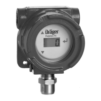
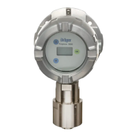
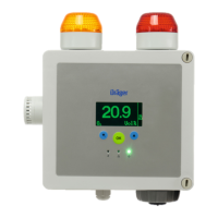
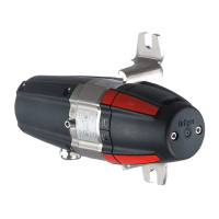
General overview of the product, referring to diagrams for component identification.
Details on the functions and features of the Polytron 8000 series gas detectors.
Purpose and intended use of the Polytron 8000 series gas detectors.
Information on certifications and approvals relevant to the product.
Instructions for installing the transmitter in an Ex d enclosure without a docking station.
Guidance on the mechanical aspects of installing the device.
Instructions for the electrical connections and wiring of the transmitter.
Table detailing the connections for various interfaces and signals.
Specific instructions for connecting and configuring the fieldbus interface.
Schematic diagrams illustrating various connection configurations for the device.
Detailed steps for connecting the fieldbus interface to the device.
Procedures for properly closing the gas detector enclosure after installation or maintenance.
Step-by-step guide for installing the EC sensor onto the Polytron 8100 EC device.
Instructions for installing various types of measuring heads.
Guidelines for selecting appropriate cable lengths for sensors installed in housings.
General guidelines and precautions to be followed before and during device commissioning.
Step-by-step procedure for the initial start-up and operation of the gas detector.
Overview of the device's control panel, including buttons and indicators.
Explanation of the different LEDs and symbols used on the device.
Description of the information displayed on the device's screen.
Explanation of display indicators common to all device types.
Specific symbols and indicators relevant to the Polytron 8100 EC model.
Details on how to interpret readings and modes displayed during operation.
Information on special operating conditions that may affect device performance.
Procedures for stopping or exiting special operating modes.
Steps to access the device's information mode for viewing details.
How to navigate through the information displayed in the information mode.
A visual representation of the device's menu structure.
Procedure for accessing specific menus within the device's interface.
Information regarding password protection for accessing certain menus or settings.
Details on the content and purpose of the Information menu.
Graphical representation of the menu structure for Polytron 8100, 8200, and 8310 models.
General guidelines and important precautions before performing calibration procedures.
Information on the types of test gases required for calibration and their properties.
Specifications for gas flow rates required during calibration procedures.
Steps and prerequisites needed before starting the calibration process.
General instructions and safety warnings related to calibration preparation.
Procedure for calibrating the device to a zero point using a test gas.
General information and prerequisites for performing zero calibration.
Step-by-step instructions for executing the zero calibration process.
General information and prerequisites for performing span calibration.
Step-by-step instructions for executing the span calibration process.
Overview of the automatic calibration feature and its benefits.
Step-by-step instructions for performing an automatic calibration cycle.
List of common faults, their causes, and recommended solutions.
List of common warnings, their causes, and recommended actions.
Procedure for verifying the detector's response to a test gas and its alarm functionality.
Detailed instructions for safely removing and installing sensors.
Specific steps for replacing sensors on the Polytron 8100 EC model.
Instructions for replacing sensors on Polytron 8200 CAT, 8310 IR, and 87x0 IR models.
Procedure for setting or changing the device's access password.
Instructions for configuring the device's internal date and time.
How to select the desired language for the device interface.
Steps to assign a specific function to the device's function key.
Procedure to reset the device to its original factory default settings.
How to adjust the contrast of the device's display for better readability.
Instructions for selecting the display mode for information presentation.
Settings for configuring the behavior of the device's relays.
Configuration options for self-holding alarms and their acknowledgement logs.
Settings for configuring the A1 and A2 relays based on normal or alarm states.
Configuration of the fault relay for heating indication.
Settings for configuring alarm behavior and parameters.
Procedure to enable or disable audible and visual alarms.
Detailed configuration options for alarm thresholds and behavior.
Steps to test the functionality of alarms and relays.
Configuration options for the device's data logging functionality.
How to view logged data as a graph of concentration over time.
Procedure to enable or disable the data logging function.
Configuring the time interval for data sampling and logging.
Selecting whether to log peak or average values.
Enabling or disabling the trigger mode for data logging.
Setting the threshold value for triggering data logging.
Configuring the stack or alternating function for data logging.
Procedure for clearing all stored data from the data logger.
Configuration settings for the 4-20 mA analog output interface.
Defining the upper and lower limits for the measurement range of the analog output.
Configuring the current value representing a fault condition for the analog output.
Details regarding the warning signal behavior and its parameters.
Procedure to enable or disable the warning signal output.
Configuring the timing and parameters of the warning signal.
Setting the current value for the warning signal output.
Configuring specific warnings related to the Dräger SensorAlive feature.
Configuring the signal output for maintenance status.
Setting the current value for the maintenance signal.
Adjusting the analog output offset value.
Adjusting the analog output span value.
Procedure for testing the functionality of the analog interface.
Configuring the signal for beam attenuation, specific to PIR 7000/7200.
Configuring the polling address for HART communication.
How to view the unique identifier for HART communication.
Setting a HART tag for device identification.
Configuring the Dräger REGARD protocol for HART communication.
Information on other available digital interfaces and their configuration.
Procedure to enable or disable the automatic calibration feature.
Settings related to the range of values captured by the sensor.
Steps to configure the capture range for sensor data.
Procedure to disable the capture range functionality.
Instructions for resetting the sensor to its default settings.
Configuring the time interval between required sensor calibrations.
Enabling or disabling the sensor lock feature.
Information about the software dongle used with EC sensors.
Steps for installing the software dongle.
Procedure to deactivate the software dongle.
Specific settings for the Polytron 8100 EC sensor.
How to perform a self-test on the sensor to check its functionality.
Configuration of gas type, measurement units, and range for the sensor.
Settings related to the Dräger SensorAlive functionality.
Specific settings for Polytron 8200 CAT and 8310 IR sensors.
Selecting the type of sensor installed in the device.
Configuring gas type, measurement units, and range for the sensor.
Enabling or disabling the DQ sensor lock function.
Specific settings for Polytron 8310 IR sensors.
Selecting the type of gas the sensor is designed to measure.
Procedure for selecting the appropriate gas type for the sensor.
Specific settings for Polytron 87x0 IR sensors.
Configuring gas type, measurement units, and range for the sensor.
Default configurations for relays, LEDs, and alarms that cannot be changed.
List of settings that can be adjusted through the device's menu system.
Values that vary based on the specific sensor installed.
Default sensor-dependent values for the Polytron 8100 EC model.
Default sensor-dependent values for Polytron 8100 EC with O2 sensors.
Default sensor-dependent values for Polytron 8100 EC with Dräger SensorAlive.
Default sensor-dependent values for Polytron 8200 CAT DrägerSensor DQ.
Default sensor-dependent values for Polytron 8200 CAT DrägerSensor LC.
Default sensor-dependent values for Polytron 8310 IR.
Default sensor-dependent values for Polytron 8700 IR.
Default sensor-dependent values for Polytron 8720 IR.
Table listing the measurement ranges for different sensor types and models.
Specifications for the analog signal output and its transmission characteristics.
Information on the properties and types of cables suitable for the device.
Details on the power supply requirements and relay specifications.
Summary of the key technical specifications for the Polytron 8xx0 series.
Operating and storage temperature, humidity, and pressure ranges.
Required torque values for securing various components during installation.
List of accessories and spare parts for the Polytron 8xx0 series.
Details and part numbers for the docking station accessory.
List of accessories and spare parts specific to the Polytron 8100 EC model.
List of SAT sensors and their corresponding part numbers.
List of accessories and spare parts specific to the Polytron 8200 CAT model.
List of accessories and spare parts specific to the Polytron 8310 IR model.
List of DSIR sensors and their corresponding part numbers.
List of accessories and spare parts specific to the Polytron 87x0 IR model.
Test certificate details according to ES, BVS 13 ATEX G 001 X standards.
Details of test certificates issued under PFG 14 G 001 X.
Conditions for the certified operation of DrägerSensor O2, O2LS, and SensorAlive.
Operating conditions for DrägerSensor O2 (6809720).
Operating conditions for DrägerSensor O2LS (6809630).
Operating conditions for Dräger SensorAlive (6809630).
FM metrological report details for DrägerSensor H2S and H2S LC.
| Ingress Protection | IP66/67 |
|---|---|
| Detection Principle | Electrochemical, Infrared, Catalytic Bead |
| Gases Detected | Combustible gases, toxic gases, and oxygen |
| Display | LCD with backlight |
| Humidity Range | 0 to 99% RH (non-condensing) |
| Housing Material | Stainless steel |
| Output Signal | 4-20 mA, HART, RS-485 Modbus |
| Power Supply | 10 to 30 V DC |
| Certifications | ATEX, IECEx, CSA |
| Temperature Range | -40 °C to +65 °C (depending on sensor) |


