- 8 -
ASSEMBLY
Your bandsaw is supplied assembled except
for the work and sanding table.To assemble
the worktable to the bandsaw:
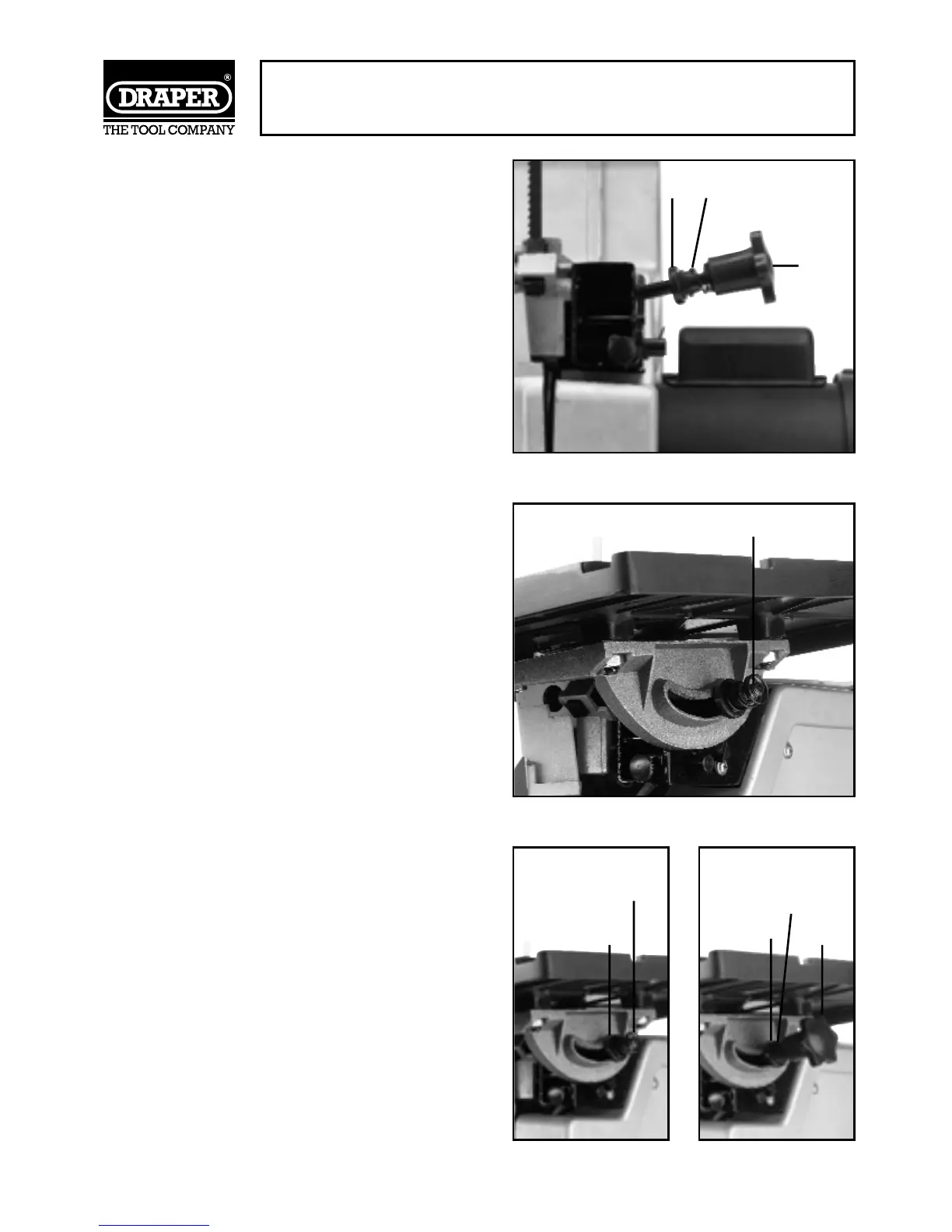
1. Remove the table lock knob $, spring
% and spring support bush & from the
table support at the rear of the bandsaw
(Fig.3).
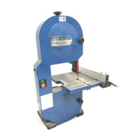
2. Remove the hex socket head table
alignment screw and clamp from the
underside of the worktable. Standing at
the rear of the of the bandsaw with the slot
of the table facing the machine, fix the
table so that the blade passes through the
table slot, and the table support rod '
goes through the curved slot in the tilt
indicator (Fig.4).
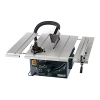
3. Replace the spring support bush & with
the large flange end facing towards the tilt
indicator.
4. Push the spring % over the spring
support bush &.
5. Screw the lock knob $ onto the table
support (Fig.5, 5A).
FASTENING TO WORKBENCH (fixing
bolts not supplied)
Your bandsaw should be bolted to a solidly
built workbench. Mounting holes are
provided in the base of the machine. Large
flat washers should be used between the bolt
heads and the base to fasten more securely
and prevent any damage to the bandsaw.
Tighten snugly but do not overtighten
SPEEDS
Your bandsaw is equipped with pulley steps
for three speeds - adequate for all normal
working requirements. Always use low speed
for cutting nonferrous metals. Medium and
high speeds are used for other materials,
depending on blade type.
Fig.3.
Fig.4.
Fig.5. Fig.5A.
& %
$
'
%
&
&
%
$