Section 7 - Tab-Tension Adjustment Procedure
Please Note: Draper’s
Tab-Tensioning System is
factory-set, and under normal
circumstances will not require
field adjustment. If wrinkles
are observed, however, follow
the adjustment procedure
shown in Figure 8.
Section 8 - Electrical Connections
1.
Screen operates on 110-120V, 60 Hz., 1.1-amp current draw.
2.
Junction box is located just above the bottom access panel at the left end
of the screen.
3.
Open the access panel/trap door for access to the junction box cover.
(See bottom access panel/trap door opening and closing instructions below)
.
4.
Remove two
(2)
hex head screws that secure the cover to the junction box
to expose the red, black, and white pigtail leads and the green ground
wire per wiring diagram
(Page 7)
.
5.
If optional low-voltage control or video interface control is specified and
factory installed, please refer to wiring diagrams
(Page 7)
.
6.
Screen ships with internal wiring complete and control switch
(es)
fully
boxed. Wire to connect screen to switch
(es)
and switch
(es)
to power
supply should be furnished by installer. Connections should be made in
accordance with attached wiring diagram, and wiring should comply with
national and local electrical codes.
7.
All operating switches should be “off” before power is connected.
Section 6 - Operation
•
110-120V SINGLE STATION CONTROL - 3-position UP-OFF-
DOWN switch permits operation to be stopped at any point. Factory
adjusted limit switches automatically stop screen when fully down
or fully up.
•
24V CONTROL
(optional and requires optional LVC-IV)
- 3-button UP-
STOP-DOWN switches stop at any point desired and operate in
any sequence. Factory adjusted limit switches automatically stop
screen when fully up or fully down. Installer should incorporate an
all-pole disconnect in fixed wiring available with RF or IR remote.
CAUTION: When operating for the first time, cycle unit down and up several times to confirm satisfactory operation. Be prepared to cut POWER if necessary.
•
RS232 / ETHERNET - Serial communication and network
communication optionally available.
•
KEY OPERATED SWITCHING - Two key-operated switches optionally
available with this unit:
•
Key-operated power supply switch controls power to screen a
and switches. When "off", switches will not operate screen. Key may
be removed from switch in either "on" or "off" position.
•
Three-position key switch permits the screen to be operated directly
by key. Requires screen operator to have a key.
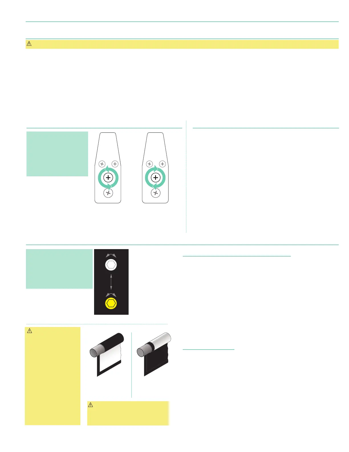
PUSH & TURN
CLOCKWISE
to INCREASE TENSION
PUSH & TURN
COUNTER-CLOCKWISE
to RELEASE TENSION
END OF
DOWEL
END OF
DOWEL
Figure 8
Section 9 - Limit Adjustments
Figure 10
Figure 9
"Down" Limit Adjustment
(requires
5/32
" (4 mm) Hex key)
To Reduce Screen Drop:
1.
Raise screen surface approximately 1'
(30 cm)
above desired setting
and turn off.
2.
Turn DOWN
(I)
limit screw clockwise
(3 screw turns =
½
roller revolution)
.
3.
Test by lowering screen. Repeat steps 1 & 2 until desired position
is reached.
To Increase Screen Drop:
1.
Lower screen to down limit.
2.
With down switch on, turn DOWN
(I)
limit screw counterclockwise
(3 screw turns = ½ roller revolution)
to increase drop.
3.
Test by raising screen approximately 1'
(30 cm)
then lower
to new down limit.
4.
Repeat steps 2 and 3 until desired position reached.
"Up" Limit Adjustment
If Screen Raises Too High:
1.
Lower screen surface approx. 1'
(30 cm)
below desired setting
and turn off.
2.
Turn UP
(II)
limit screw clockwise
(3 screw turns = ½ roller revolution).
3.
Test by advancing screen up.
4.
Repeat steps 1 through 3 until desired position is reached.
If Screen Needs to Raise Higher:
1.
Lower screen surface approx. 1'
(30 cm)
below desired setting
and turn off.
2.
With UP switch on, turn UP
(II)
limit screw counterclockwise
(3 screw turns =
½
roller revolution)
.
3.
Repeat steps 1 and 2 until desired position is reached.
Please Note: Screen limits
are factory set for optimum
performance of the screen.
Any adjustment of these limits
could void the warranty.
Please check with Draper
prior to resetting screen limits.
CAUTION:
- Be sure all switches
are in “off” position
before adjusting limit
switches.
- Be prepared to shut off
manually while testing.
- Screen may be
damaged by lowering
it too far and
exposing roller.
- Motor must be
installed so that limit
switches are pointed
down.
Left hand motor:
White Socket—Down
Yellow Socket—Up
Right hand motor:
White Socket—Up
Yellow Socket—Down
Left hand motor:
White Socket—Up
Yellow Socket—Down
Right hand motor:
White Socket—Down
Yellow Socket—Up
White Socket—Down
White Socket—Up
Yellow Socket—Down
W
d Roll
Motor
End
Audience
Side
Reverse Roll
Motor
End
Back
Side
lI
I
+
+
DOWN Limit (I)
Clockwise decreases
down travel.
UP Limit (II)
Counterclockwise
increases up travel.
DOWN Limit
(I)
:
Clockwise
decreases
down travel.
UP Limit
(II)
:
Counterclockwise
increases
up travel.
CAUTION:
DO NOT allow dowel to wrap over
roller when operating screen!
This could damage screen.
page 5 of 7
Ultimate Access E and V