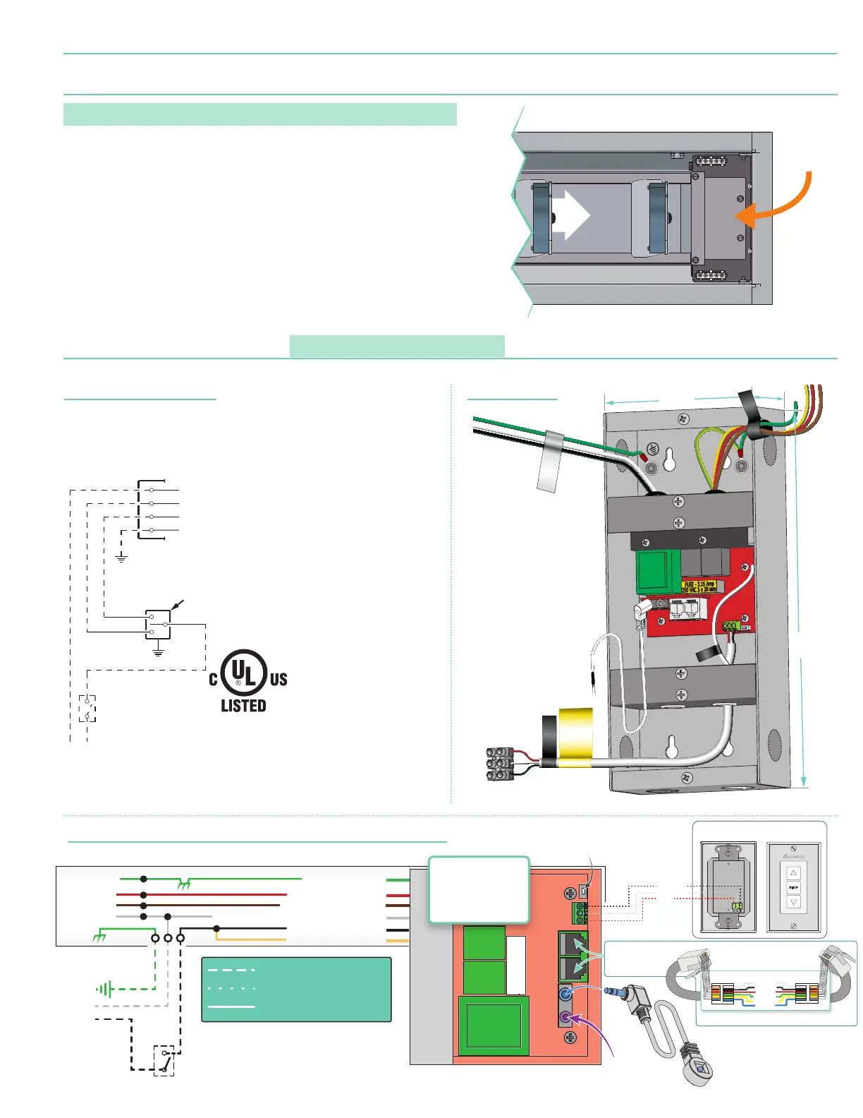
Section 13 - Accessing Built-In Low-Voltage Control Unit
(LVC-IV)
PLEASE NOTE: Applies ONLY if Unit is built into case.
1..
Locate junction box on motor end of screen.
(Fig. 11)
.
2.
Remove the four
(4)
hex head screws from the junction box.
3.
Remove the L-bracket with the LVC-IV from the junction box.
LVC-IV Unit
Location
(Bottom View)
Figure 11
INTERNAL SCREEN WIRING
FUSE - 3.15 AMP
250 VAC 5x20mm
N
Location of key operated
ON-OFF SWITCH (if supplied)
L1
GND
Black-to 110V-120V AC-Hot
Red-to screen (directional)
Brown-to screen (directional)
Yellow-to 110V-120V AC-Hot
White-Common to screen & 110V-120V AC Neutral
Green/Yellow (Ground)
White (Common)
Red (Up)
Black (Down)
Green/Yellow
(Motor Ground)
Low-Voltage
Trigger
4-28 VDC
LVC-S: 3 BUTTON WALL SWITCH
PN: 121225
BACK
BLACK - DOWN
WHITE - COMMON
RED - UP
IR Eye
Input
IR Eye
Max Cable Length:
42” (1 meter)
RS232/485
Inputs/Outputs
(Ports are identical)
Data Cable to more LVC-IV Modules (6 Max)
RJ25
Connector
RJ25
Connector
ELECTRICALLY STRAIGHT DATA CABLE
1 - WHITE -1
2 - BLACK - 2
3 - RED - 3
4 - GREEN - 4
5 - YELLOW - 5
6 - BLUE - 6
Receiver
Button
FACTORY WIRING
Low-Voltage wiring by Others
DASHED WIRING BY ELECTRICIAN
Internal
LVC-IV
Internal LVC-IV - Single or Multiple Projection Screen Wiring Diagram
2.214"
(56mm)
4.5"
(114mm)
10.39"
(264mm)
MOTOR LEADS
WALL SWITCH
AC POWER INPUT
WARNING
DRY CONTACT
CLOSURE ONLY.
APPLYING VOLTAGE
HERE WILL DAMAGE
CONTROLLER.
RF Antenna
Wire
External LVC-IVStandard and Quiet Motors
Single Station Control
White (Common)
Black (Down)
Red (Up)
Green (Ground)
Control
switch
Blue
Black
Red
Location of key
operated on-off
switch if furnished.
Single gang box by others.
Min. 4" x 21⁄8" x 17⁄8" deep.
(102mm x 54mm x 48mm)
Dashed wiring
by electrician.
Internal Screen Wiring
STANDARD
Section 14 - Wiring Diagrams
Please Note: Do not wire motors in parallel.
page 7 of 7
Ultimate Access E and V