4
4
.
.
I
I
n
n
s
s
t
t
a
a
l
l
l
l
i
i
n
n
g
g
y
y
o
o
u
u
r
r
V
V
i
i
g
g
o
o
r
r
2
2
7
7
6
6
2
2
r
r
o
o
u
u
t
t
e
e
r
r
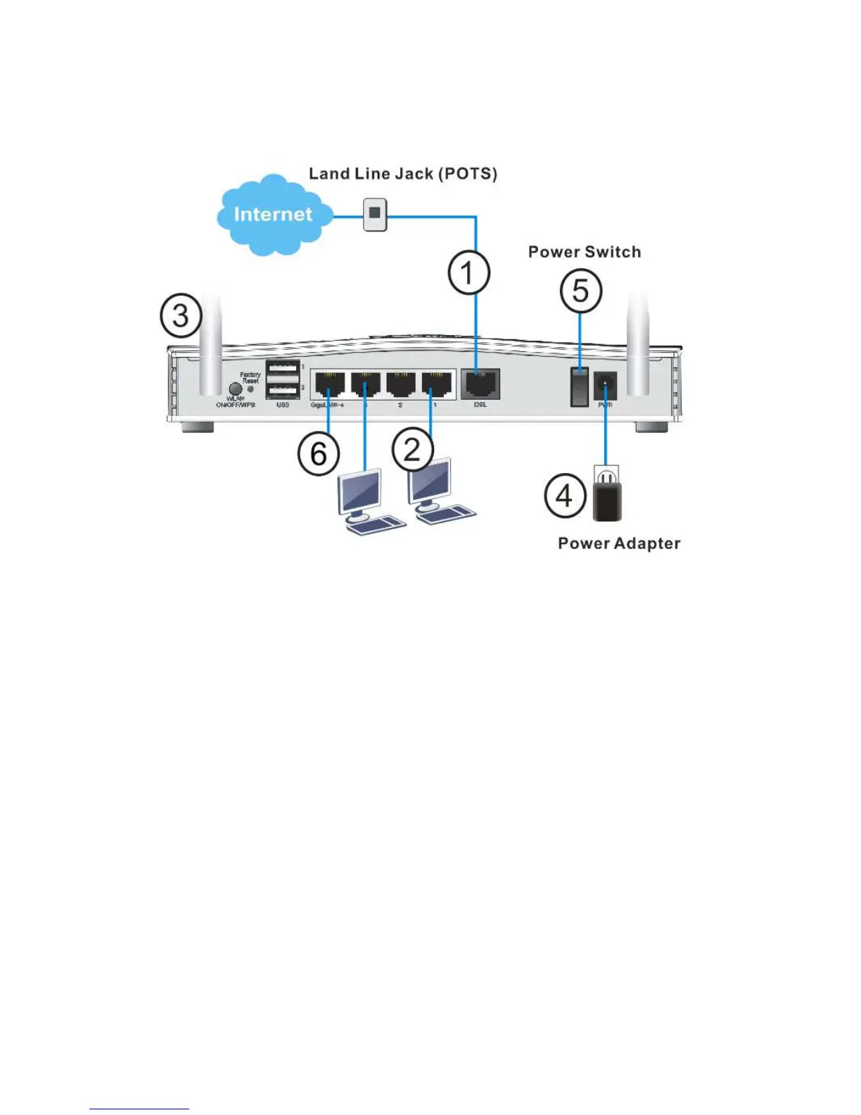
1. ADSL/VDSL Connections: Connect the DSL port to the Modem or DSL port of the
external splitter/microfilter (not supplied) with the RJ-11 line cable. In some
cases, your RJ-11 DSL socket will be built-into your phone line socket on the wall
and you won’t have a separate microfilter/splitter.
2. LAN Connections: Connect a LAN port of the router to your computer or switch.
3. Wireless Antennas: Connect the wireless antennas to the router
4. Power Supply: Connect the power adapter to the Vigor 2762’s PWR socket on
the rear and plug the power adapter into a suitable mains socket.
Turn the Vigor 2762 on using its power switch.
5. The router will start up. After completing the system test, the ACT LED will light
up and start blinking once per second to indicate that it is ready for use.
For more detailed information of LED status, please refer to section 3.1 Front
Panel Overview.
6. Ethernet-based Internet Connections: The GigaLAN4 port can be switched to
operate as the Ethernet WAN port. This must be configured in the router’s web
interface before it can operate in this mode – Section 5.3 of Quick Start Guide
details how to do that.
With the GigaLAN4 port configured for Ethernet WAN mode, connect the cable
Modem/DSL Modem/Media Converter to the WAN port of the router with
Ethernet cable (RJ-45).