13
Assembly Instructions
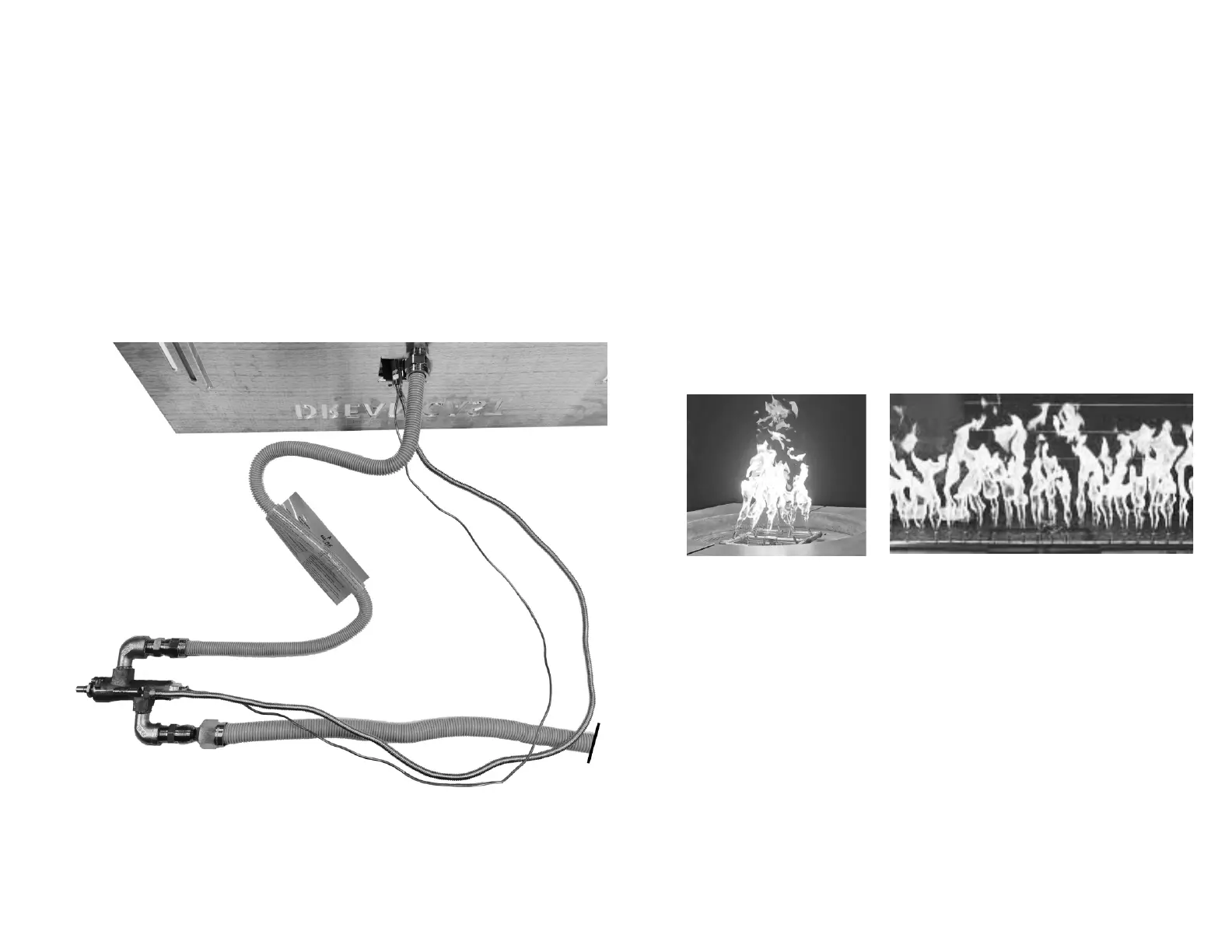
7. Connect Control Valve to Burner Assembly
Place the aluminum plate on a blanket, or have someone hold it,
in a position where the remaining connections can be made.
A) Connect the flex hose from the Control Valve burner outlet to
the flared fitting on the Burner inlet.
B) Connect the Thermocouple Line from the Pilot Assembly to the
Control Valve thermocouple port.
C) Connect the Pilot Line from the Pilot Assembly to the Control
Valve pilot outlet.
Carefully lower the Aluminum Plate Assembly into the firepit,
taking care not to kink or crush any of the lines.
8. Test the Assembly
Check all connections for leaks with leak detector or leak reactant
on main gas supply and repair leaks as necessary.
Light the fire pit following the instructions in “Operating
Instructions” on page 15.
Visually inspect the Pilot flame. Pilot flame should cover the
thermocouple by 3/8" to 1/2". Adjust as necessary.
Visually inspect Burner flame pattern. Flames should be steady
and consistent throughout the burner.
Refer to the “Troubleshooting Guide” on page 16 to resolve any
issues.
9. Install the Firepit Media
Install the Firepit Media following the instructions in “Media
Installation” on page 12.
Test the fire pit one more time after installing the media.
⚠WARNING: Test all gas piping and connections for leaks after installing
or servicing. Correct all leaks immediately.
to Gas
Supply:
B)
C)
A)
Typical Flame Patterns: