12
Assembly Instructions
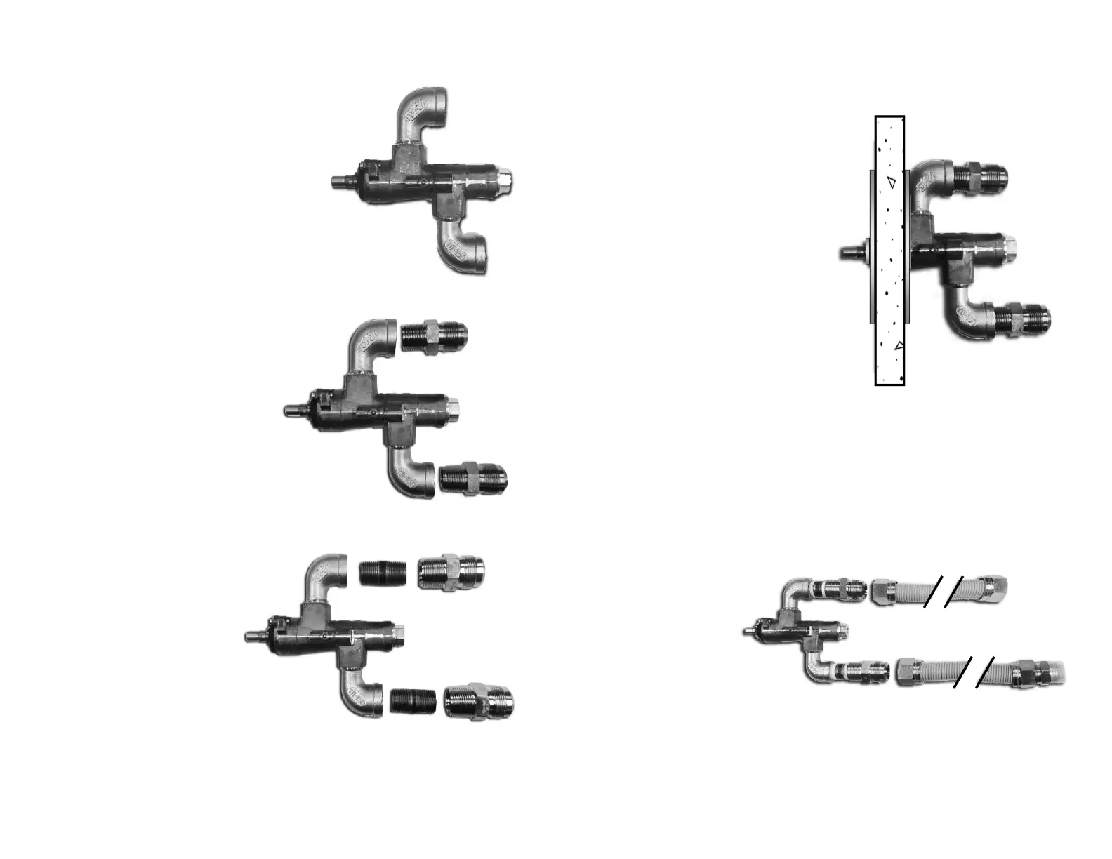
4. Assemble The Control Valve
Install the 2x street elbow fittings
into the Control Valve so that
they are oriented in the same
direction as the pilot and
thermocouple ports.
50k-199k BTU SYSTEMS:
Install one flared fitting into
the each street elbow.
-OR-
200k-250k BTU SYSTEMS:
Install one 1/2" Nipple
into each street elbow,
then install one flared
fitting onto each 1/2"
nipple.
5. Mount Control Valve onto Fire Pit
Attach the Control Valve
Mounting Plate to the outside
of the firepit using the supplied
bolts and backing plate.
Ensure the printed markings on
the mounting plate are oriented
correctly.
Remove the threaded nut from
the front of the Control Valve.
Place the Control Valve inside
the firepit, through the
mounting plate, and secure it
with the threaded nut.
Ensure that the Pilot
Adjustment valve is on top and
can be accessed from the outside, through the hole in the
mounting plate.
6. Connect Control Valve to Gas Supply
Install the two Flex Hoses onto the two flared fittings that are
installed on the Control Valve.
Connect your gas
supply to the inlet
side of the Control
Valve.
DreamCast High-
BTU fire pits are not
certified for use with portable propane tanks. They must be
connected to a fixed fuel piping system.
to Gas Supply:
to Burner: