EasyManua.ls Logo

Dri-Eaz F412-115V User Manual

Dri-Eaz F412-115V
36 pages
To Next Page IconTo Next Page
Page #1 background imageLoading...
Page #1 background image
07-01776H F412-115V 1 Dri-Eaz Products, Inc.
Owners Manual
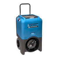
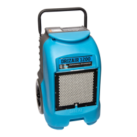
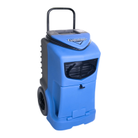
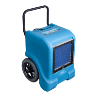
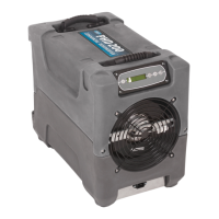
LGR 7000XLi Portable Dehumidifier
Model F412-115V
DRI-EAZ PRODUCTS, INC.
15180 Josh Wilson Road, Burlington, WA 98233
Phone: 800-932-3030 Fax: 360-757-7950 www.dri-eaz.com
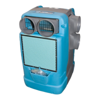
The Dri-Eaz® LGR 7000XLi dehumidifier reduces humidity in enclosed environments by
removing water vapor from the air. The 7000XLi is rugged, durable and highly portable, making
it ideal for water damage restoration, structural drying, construction, and other applications
requiring temporary, high-performance dehumidification.
Patents: http://www.LBpatents.com
S A V E T H E S E I N S T R U C T I O N S
SAFETY INSTRUCTIONS
WARNING! Do not alter or modify your dehumidifier
in any way. Use only replacement parts authorized
by Dri-Eaz Products, Inc. Modifications or use of
unapproved parts could create a hazard and will
void your warranty. Contact your authorized
distributor for assistance.
WARNING! Electric shock hazard, rotating fan, hot
surface hazards. Unplug unit before opening cover
for cleaning or servicing. Unit must be grounded.
Inspect the power cord before use. If cord is
damaged, do not use. Always grasp the plug (not the
cord) to unplug.
Insert three-prong plug on power cord into a
matching electrically grounded outlet. Do not use
adapter. Never cut off third prong. Do not use an
extension cord.
The unit must be operated on a 115V/60Hz circuit
protected by a Ground Fault Circuit Interrupter
(GFCI) device.
Keep motor and wiring dry.
Do not attempt to repair the unit. For Authorized
Service Centers, contact Dri-Eaz.
BEFORE YOU BEGIN
Warranty registration
Visit warranty.drieaz.com to register your purchase.
Registration allows us to better assist you with using,
maintaining or servicing your equipment and to contact
you in case we have important safety information
concerning your Dri-Eaz product. If you determine
service is required, have your equipment model, serial
number and original proof of purchase available and call
your distributor for assistance with obtaining a return
material authorization (RMA).
WARNING
CORRECT PLUG REMOVAL
Grasp IEC plug and pull straight out
IMPORTANT: Damage to IEC receptacle or
dehumidifier resulting from improper
removal of the power cord is not covered by
warranty. The IEC power cord is a wear item
and is not covered by warranty.

Questions and Answers:

Dri-Eaz F412-115V Specifications

General IconGeneral
ModelF412-115V
CategoryDehumidifier
Voltage115V
PumpYes
Continuous Drain OptionYes
Airflow (CFM)235 CFM
Operating Temperature Range33°F to 100°F

Summary

Safety Warnings and Precautions

General Warning

Electric shock hazard, rotating fan, hot surface hazards. Unplug unit before opening cover for cleaning or servicing.

Safety Instructions

Do not alter or modify your dehumidifier. Use only authorized replacement parts to avoid hazards and warranty voiding.

Correct Plug Removal

Grasp IEC plug and pull straight out. Improper removal may damage the unit and void warranty.

Getting Started

Warranty Registration

Register your purchase online to receive better assistance and important safety information about your product.

Parts Identification

Front Components

Identifies front components including humid air inlet, HAF filter, and molded pocket for cord storage.

Rear Components

Identifies rear components such as integrated handle, control panel, and drain hose pocket.

Power Attachment Point

Shows the location of the product label, serial number, and power cord socket.

Operating Instructions

Set Unit Upright

Proper orientation for transporting/storing to prevent compressor oil issues and damage.

Positioning a Dehumidifier

Operate in enclosed areas away from obstructions for optimal water removal efficiency.

Setup Procedures

Set Up Drain Hose

Connect condensate pump to drainage hose, ensure it's uncoiled and unobstructed for safe water drainage.

Plug In Electrical Cord

Connect to GFCI-protected 115V/15A outlet. Plug unit first, then outlet for safety.

Turn On Unit

Press the ON/OFF button to start the dehumidifier. Unit may perform a delay sequence.

Control Panel Operation

Control Panel Overview

Describes the display and touchpad keys: ON/OFF, DISPLAY MENU, MENU SELECTION, PURGE PUMP.

Startup and Display Modes

Explains initial self-diagnosis, normal display readings, and operating hours tracking.

User Settings and System Information

Access and adjust settings, view system data via the DISPLAY MENU key.

Error Messages

Indicates when onboard diagnostics detect a problem; refer to the error message section for details.

User Settings Menu Details

Job Hours Reset

Resets the total operating hours counter for job tracking purposes.

Inlet/Outlet and Grain DPR

Displays inlet/outlet conditions and grain per pound values for monitoring.

Filter and Coil Cleaning Status

Shows hours since filter/coil cleaning and allows for resetting these indicators.

Humidistat Settings

Allows adjustment of humidistat mode and setpoint for precise humidity control.

Language and Temperature Units

Select display language and preferred temperature units (°F or °C).

Additional Information Items

Displays coil temperature, compressor current, firmware version, and life hours.

Operational Procedures

At The End Of The Job

Steps to ensure all water is removed from the unit before moving it to prevent drips.

Handling and Maintenance

Transportation and Storage

Guidelines for careful handling, avoiding horizontal positions, and securing during transport.

Maintenance Schedule Overview

Lists tools and supplies needed for various maintenance procedures outlined in the manual.

Maintenance and Cleaning

Maintenance Checks

Covers checks before use, monthly inspections, and as-needed cleaning of components like pump and coils.

About 3M HAF Filters

Explains filter guidelines, replacement frequency, and precautions for optimal filtration.

Cleaning Coils and Heat Exchange Block

Instructions for cleaning coils and the heat exchange block to maintain unit efficiency.

Component Installation and Operation

Installing the HAF Filter

Guide on correctly orienting the HAF filter during installation to prevent damage.

Pump Purge Button Function

Explains the control panel message for pump purging and how to stop it if needed.

System Messages and Status

System Status Indicators

Lists control panel messages like INITIALIZING, FIRMWARE VERSION, and PLEASE WAIT.

Operating Mode Messages

Describes messages for UNIT ON, HUMIDISTAT, LOW TEMP, and HI TEMP cycle status.

Cycle and Cleaning Prompts

Explains messages for DEFROST, UNIT DRYING, CLEAN FILTER, and CLEAN COILS prompts.

Troubleshooting Error Messages

Sensor Errors

Explains ER4 (temp sensor) and ER5 (inlet temp/RH sensor) errors and their solutions.

Service and Model Errors

Covers ER6 (contact service) and ER7 (invalid model setting) errors and their resolutions.

Button and Pump Errors

Details ER8 (stuck button) and ER9 (pump blocked) errors and troubleshooting steps.

Troubleshooting Guide

Common Faults and Solutions

Lists common issues like water drips, unit not operating, poor drying, and their causes/solutions.

Product Specifications

Technical Specifications

Details model, weight, dimensions, power, water removal rates, air filter, and safety certifications.

Electrical Schematics

High Voltage Schematic

Diagram showing high voltage electrical components, power inputs, and connections.

Low Voltage and Control Schematic

Diagram illustrating low voltage, control panel, sensors, and optional component connections.

Related product manuals