3
VAPORMIST INSTALLATION, OPERATION, AND MAINTENANCE MANUAL
Product overview
OVERVIEW
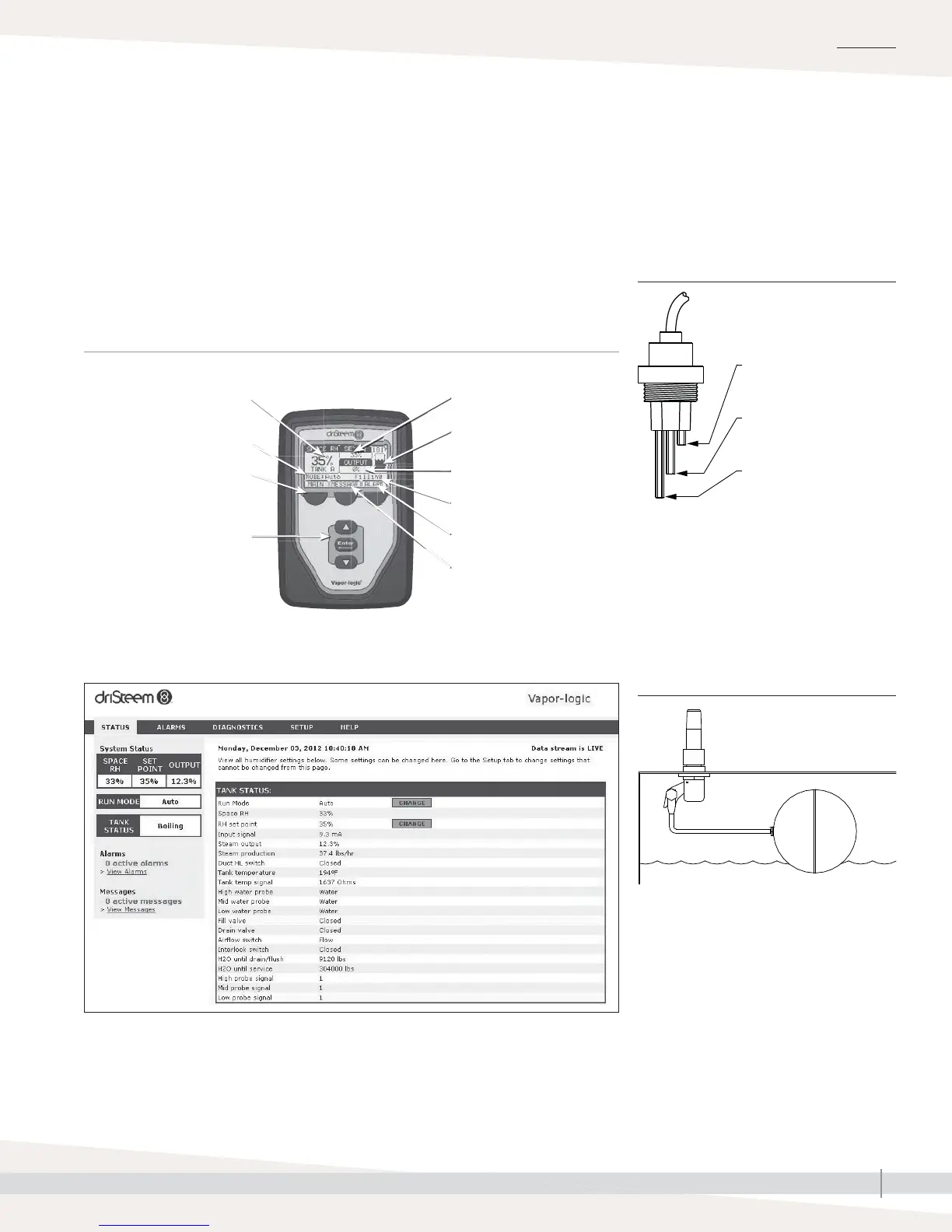
CONTROLLER
The Vapor-logic controller in Vapormist humidifi ers provides menus for all
humidifi er functions, with a Web interface for Ethernet access (see Figure 3-1).
The Vapor-logic version 5 Installation and Operation Manual ships with
Vapormist humidifi ers. Refer to it for information on using the keypad/display
and Web interface, and for troubleshooting information.
WEB INTERFACE
Notes:
See Pages 10 and 11 for detailed installation
drawings.
Humidifi ers using tap or softened water control
water levels electronically using a three-rod
probe. The controller responds with the above
actions when the water level reaches each rod.
VLC-OM-030
Fill valve opens when
water level is below this
probe.
Low-water cutoff. Power to
heaters is cut if water level
drops below this probe.
Fill valve closes when water
level rises to this probe.
mc_030910_1335
FIGURE 3-2: WATER LEVEL CONTROL
FOR TAP/SOFTENED WATER HUMIDIFIER
Supply water connection
Float rod
Float ball
OM-7396
Humidifi ers using RO/DI water control water
levels using a fl oat valve and low-water cutoff
switch.
mc_052710_1644
FIGURE 3-3: WATER LEVEL CONTROL
FOR RO/DI WATER OPTION HUMIDIFIER
Softkeys
for direct menu access
Navigation buttons
for item selection
System alarms
Tank status
Set point
System messages
Mode
Room RH
Steam output
Tank water level
KEYPAD/DISPLAY
FIGURE 3-1: VAPOR-LOGIC KEYPAD/DISPLAY AND WEB INTERFACE
 Loading...