20
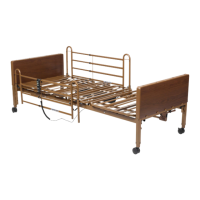
A6. Once in place, replace the motor covers to secure the motor.
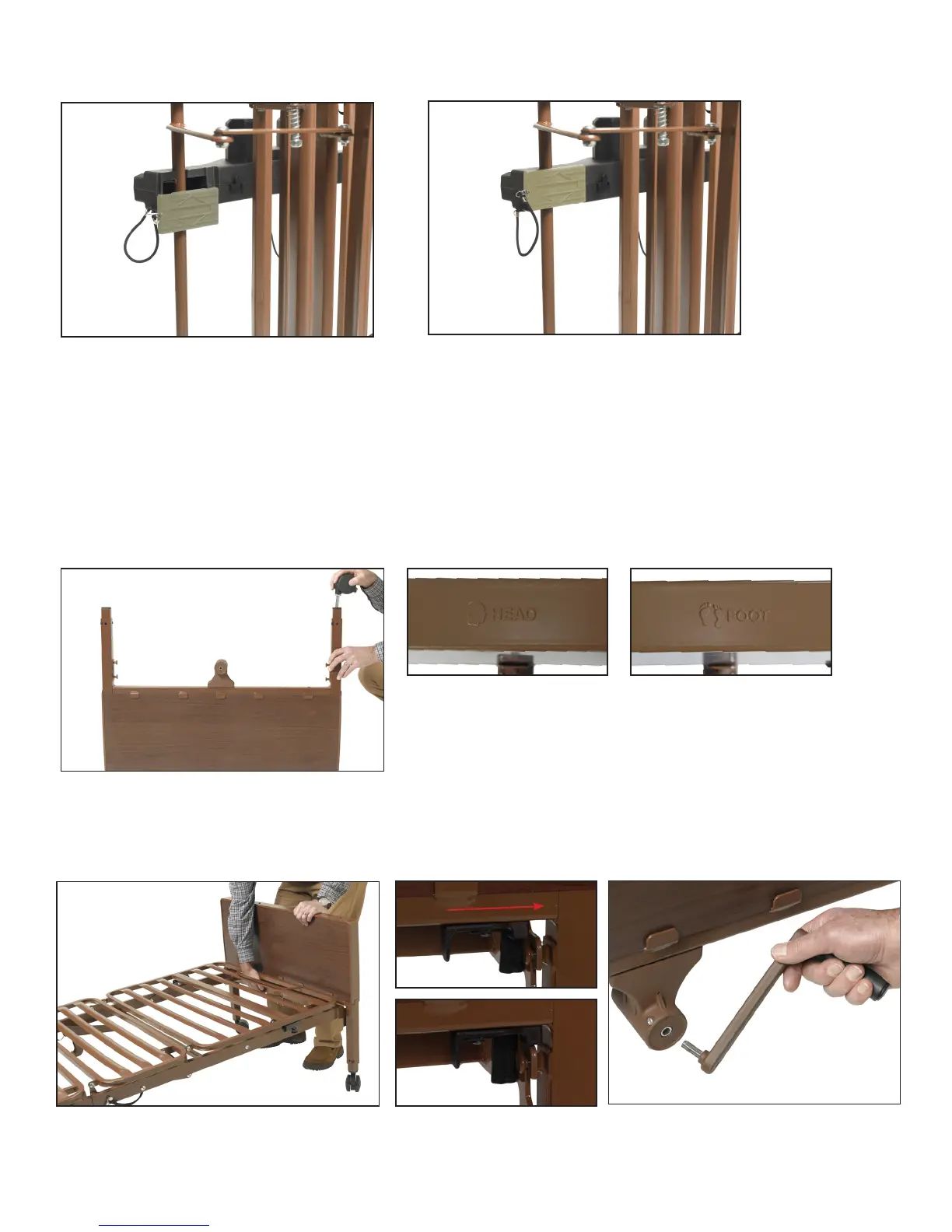
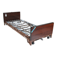
A7. Assemble Bed Ends to Frame: #15571HF for Crank Hi/Lo Beds Ends or #15561HF for Manual Adjustment Bed Ends.
Once the motor is attached, lay bed at and install head and foot boards. Foot end of the bed frame has the mattress
retainer. Lift mattress retainer to help keep mattress in place. Gear box crank connection will always face outward –
away from the bed.
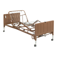
Install casters onto 15571HF Bed ends by inserting the stem of the caster into the leg receptacle. It is recommended
to install one locking caster and one non-locking caster on each bed end. The locking casters should be installed di-
agonally from each other. Install casters to both bed ends. To engage locking caster, press down on locking tab; lift up
to release. 15561HF bed ends do not include casters, casters are an option.
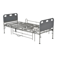
Attach the 15571HF or 15561HF Head and Foot Boards by aligning the frame mounting hooks over bed end mounting
pins and push frame down to secure in place. Push Slide Locks in place over frame hooks for both bed ends to help pre-
vent frame separation from bed ends.