?Pass each ignition cover screw through each aligned hole, and thread each nut onto
Take the ignition cover and position it so that it's centered over the handlebar clamp
1716
Step three: Installing the ignition key cover
• Locate the ignition key cover (attached to the frame), pre-installed ignition cover
screws (x 2) and nuts (x2), 3 mm allen wrench, and 7 mm wrench.
•
•
Ensure that the ignition cable is lying in the center, beneath the handlebar.
•
Ensure the ignition screw holes (on each edge of the ignition cover) are aligned with
each screw from the bottom.
•
?While using the 7 mm wrench to brace against the nut, use the 3 mm allen wrench to
•
?Ensure that the ignition cover is fully & tightly installed by pulling on it. There should be
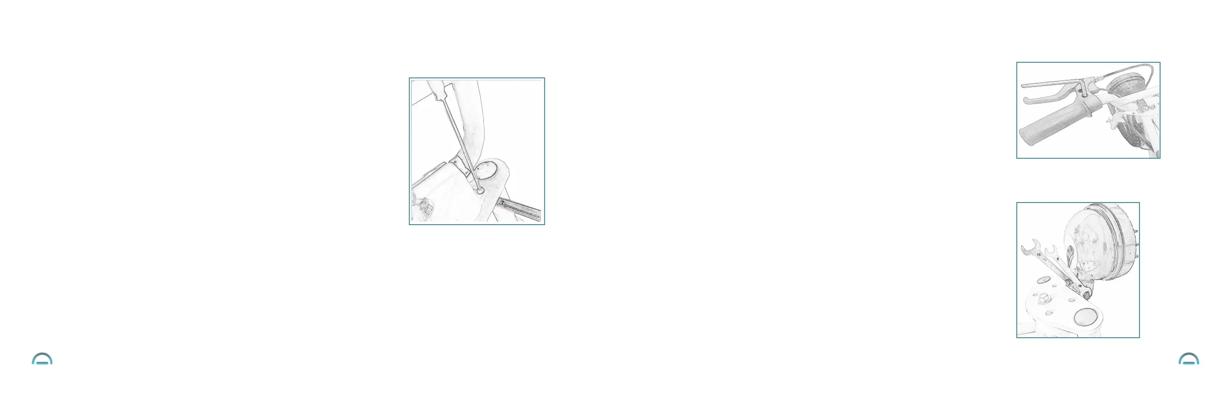
Step four: Tightening the brake lever
• Locate the brake lever and 5 mm allen wrench.
• The brake lever is already pre-installed on the left side of the handlebar,
with the lever facing outward.
•
?Using the 5 mm allen wrench, tighten the brake lever screw from the top, as shown
in the diagram.
•
Ensure that the brake lever is fully and tightly installed by pulling on it.
There should be no looseness.
Step five: Adjusting the headlight
• Locate the 10 mm wrench and 13 mm wrench.
• The headlight is already pre-installed onto the frame, folded in the
downward position.
• Fold the headlight up, so the headlight is facing outward.
• Locate the pre-installed screw and nut at the base of the headlight.
• ?While using the 13 mm wrench to brace against the screw, use the 10 mm wrench
to tighten the nut.
• Ensure that the headlight is fully and tightly installed by pulling on it.
There should be no looseness.
• The headlight switch is located beneath the battery level indicator on the
right handlebar. (Note that the headlight switch will NOT turn on the headlight
while the product is powered off.)
• Remove both pre-installed ignition cover screws and nuts.
(as shown in the diagram).
no looseness.
•
tighten the screw.
the corresponding holes on the frame below.