1
Introduction
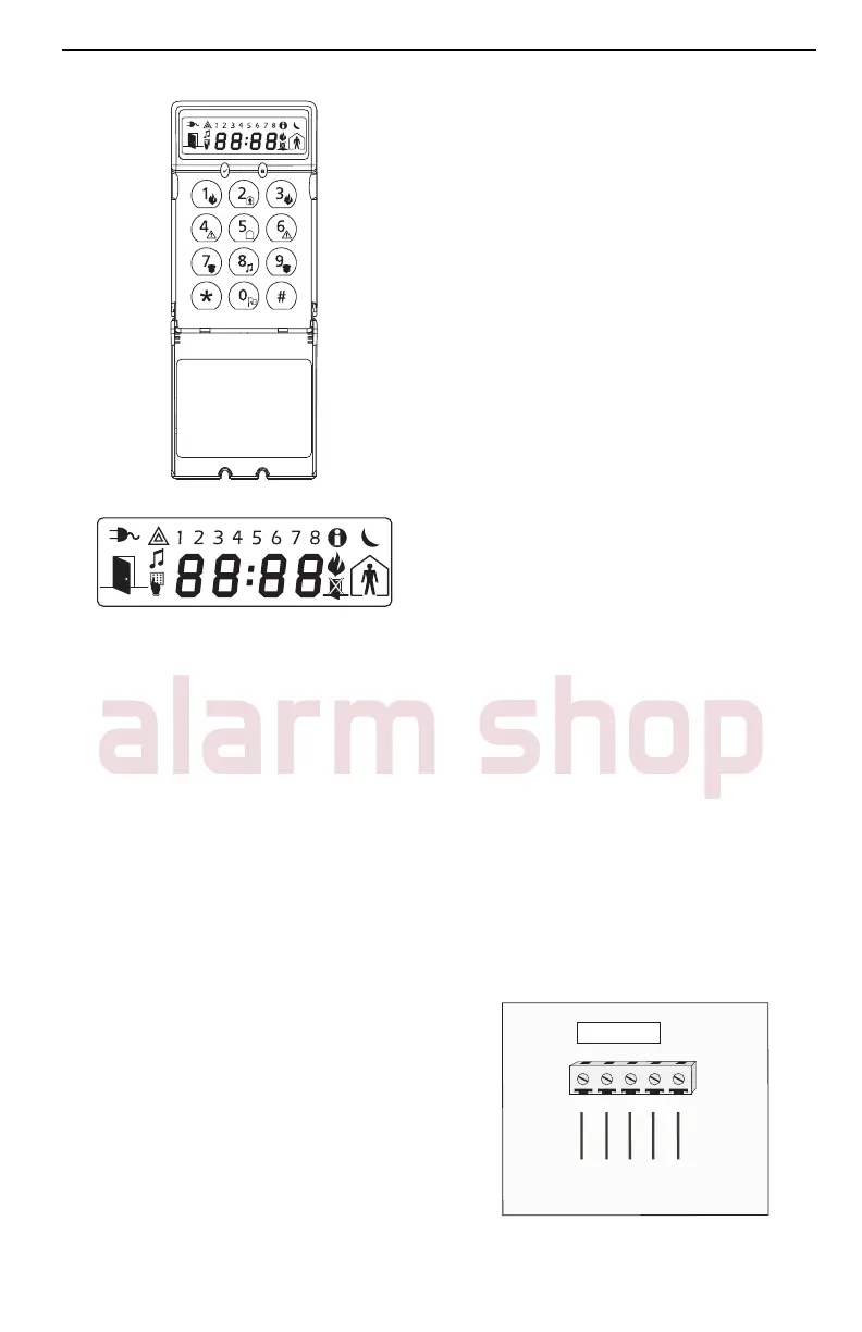
The LCD5511 keypad presents system
status using an LCD display along with
symbols and numbers. The keypad can
be used on security systems with up to
64 zones. The LCD5511 is compatible
with the following DSC security systems:
• PC580/PC585 • PC5008
• PC1555/PC1565 • PC50XX
Specifications
• Voltage rating: 12V
DC
nominal
• Connects to control panel via 4-wire
Keybus
• One keypad zone input/PGM output
• Current draw: 22mA (standby) / 85mA
(maximum)
• Optional tamper version
• Four programmable function keys
• Ready (green) and Armed (red) status
lights
• Low temperature sensor
Installation
Unpacking
The LCD5511 package includes the fol-
lowing parts:
• One LCD5511 keypad
• Four mounting screws
• one end-of-line resistor
• three keypad inner door labels
• one tamper switch
• surface tape
• one user Instruction Manual
• one Installation Manual
Mounting
You should mount the keypad where it is
accessible to designated points of entry
and exit. Once you have selected a dry
and secure location, perform the follow-
ing steps to mount the keypad.
Remove the keypad backplate by
loosening the screw (optional) located
at the base of the unit.
Secure the keypad backplate to the
wall in the desired location. Use the
screws provided.
To use the keypad tamper, insert the
tamper switch supplied into the opening
located in the centre of the backplate.
For tamper use, try to ensure the back-
plate is mounted on a smooth, flat sur-
face. If mounting on a rough surface,
fasten the enclosed surface tape to
the wall to even out the surface area
where the tamper will be positioned.
Before attaching the keypad to its
backplate, complete the keypad wir-
ing as described in the next section.
Wiring
1. Before wiring the unit, ensure that all
power (AC transformer and battery) is
disconnected from the control panel.
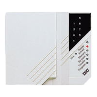
2. Connect the four Keybus wires from
the control panel (red, black, yellow
and green) to the keypad terminals (R
B Y G). Consult the diagram below:
RED BLK YEL GRN
To Zone Input/
PGM Output
RBYG
Z/P
LCD5511