OUTPUT SOURCE LIST
0 Not used
1 RESERVED 3
2 Arm safety on alarms
3 Audible alarm
4 Battery over volts warning
5 Battery under volts warning
6 Can ECU data fail
7 Can ECU
10 Can ECU stop
11 Charge alternator shutdown
12 Charge alternator warning
13 Close gen output
14 Close gen output pulse
15 Close mains output
16 Close mains output pulse
17 Combined mains failure
21 Common warning
22 RESERVED
23 RESERVED
24 RESERVED
25 RESERVED
26 RESERVED
27 RESERVED
28 RESERVED
29 Emergency stop
31 RESERVED
32 RESERVED
33
36 Generator available
37 Generator over voltage shutdown
38 RESERVED
39 RESERVED
40 Loss of magnetic pickup signal
41
42 RESERVED
43 RESERVED
44 RESERVED
45 RESERVED
46 RESERVED
47 Open gen output
48 Open gen output pulse
49 Open mains output
50 Open mains output pulse
51 RESERVED
52 RESERVED
53
Preheat during preheat timer
Preheat until end of crank
Preheat until end of safety timer
Preheat until end of warming timer
59 RESERVED
60 RESERVED
61 Waiting for manual restore
62 Flexible sender High Shutdown
63 Flexible sender High Warning
64 Flexible sender Low Warning
65 Flexible sender Low Shutdown
44xx
02 (CAN option) only
44xx
01 (Magnetic pickup option) only
TYPICAL WIRING DIAGRAM
053-079 ISS 5
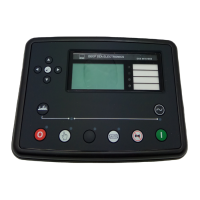
D E E P S E A E L E C T R O N I C S
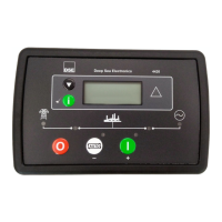
DSE4420 INSTALLATION INSTRUCTIONS
This instruction sheet is for DSE4420 MKII controllers only.
For DSE4420 controllers below version 2 use DSE publication
053-056
ACCESSING THE FRONT PANEL CONFIGURATION EDITOR
Ensure the engine is at rest and the module is in stop mode by
pressing the stop/reset button.
Press the stop/reset and down buttons simultaneously.
The configuration icon is displayed, along with the first
configurable parameter.
EDITING A PARAMETER
Press to select the required ‘page’ as detailed in the
configuration tables.
Press (+) to select the next parameter or (-) to select the
previous parameter within the current page.
When viewing the parameter to be changed, press the button.
The value begins to flash.
Press (+) or (-) to adjust the value to the required setting.
Press the save the current value, the value ceases flashing.
Press and hold the button to exit the editor, the configuration
icon will be removed from the display.
NOTE: - pressing and holding the + / - buttons will give auto-
repeat functionality. Large values can be changed quicker by holding
the buttons for a prolonged period. For instance large timers
increment in 1 second steps to 1 minute, then in 30 second steps to
1 hour, then in 30 minute steps.
DIMENSIONS AND MOUNTING
For flat surface mounting in a Type 1 enclosure to meet UL
requirements.
DIMENSIONS
180mm x 116mm x 42mm
(7.1” x 4.6” x 1.7”)
PANEL CUTOUT
154mm x 98mm
(6” x 3.9”)
Deep Sea Electronics Plc.
Tel:+44 (0)1723 890099
Fax: +44 (0)1723 893303
Email: support@deepseaplc.com
Web: www.deepseaplc.com
Deep Sea Electronics inc.
Phone: +1 (815) 316-8706
Fax: +1 (815) 316- 8708
TOLL FREE (USA only) :
Tel: 1 866 636 9703
Email: support@deepseausa.com
Web: www.deepseausa.com
DSE4420
http://bestgenerator.spb.ru/?page_id=6765