Do you have a question about the DSE DSE7210 and is the answer not in the manual?
Lists installation guides for various DSE products, serving as initial setup references.
Lists DSE manuals and relevant external standards for detailed technical information.
Introduces the DSE7000 series modules, highlighting their functionality and design for generator control.
Explains the convention for identifying DSE7000 series controllers by part numbers and model designations.
Outlines DC supply voltage, current, and voltage/frequency sensing specifications for the controllers.
Details current sensing, digital/analogue inputs, and types of DC and relay outputs available.
Covers USB, RS232, RS485, and CAN port specifications and DSENet® for expansion modules.
Provides physical dimensions, mounting details, and relevant industry standards and enclosure ratings.
Provides a guide to rear module connections, terminal functions for power, sensors, and outputs.
Presents example wiring configurations for different system topologies and controller models.
Illustrates the typical connection layout for host controllers and expansion modules via the DSENet® system.
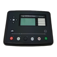
Explains the functions of buttons, LEDs, and the display on the DSE7210/DSE7310 autostart module.
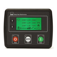
Describes the controls, buttons, and LEDs on the DSE7220/DSE7320 auto mains failure module.
Guides on starting/stopping the engine, and navigating instrument pages for status and parameters.
Details the function of each control button on the module, such as Stop/Reset, Manual, Auto, and Start.
Discusses system configurations like frequency selection and different operation modes (Auto, Manual, Test).
Explains dummy load/load shedding control and sending SMS commands for remote operation.
Details the sequences for starting, running, and stopping the generator in Auto, Manual, and Test modes.
Explains how two controllers operate as Master/Slave for generator standby and load balancing.
Details disabling shutdown/trip alarms and handling CAN, indications, warnings, and shutdowns.
Explains high current, earth fault, and short circuit protection mechanisms using IDMT curves.
Covers maintenance alarms, scheduling, and accessing front panel and running configuration editors.
Lists essential pre-start checks for wiring, power supply, and system readiness before initial operation.
Provides a guide to common symptoms and their possible solutions for troubleshooting module and engine issues.
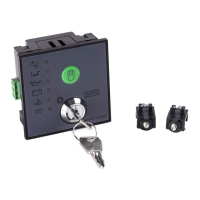
Lists part numbers for connector plugs, fixing clips, and sealing gaskets available from DSE.
Details compatible expansion modules and Ethernet/LAN connection adapters for extended functionality.
Outlines regulations for the disposal of electrical equipment and hazardous substances.
| Maximum Operating Current | 340 mA at 12 V, 160 mA at 24 V |
|---|---|
| Maximum Standby Current | 160 mA at 12 V, 80 mA at 24 V |
| Generator & Mains (Utility) Frequency | 3.5 Hz to 75 Hz |
| Magnetic Pick-up Frequency | 10, 000 Hz (max) |
| Storage Temperature Range | -40 °C to +85 °C |
| Maximum Humidity | 95% non-condensing |
| Display | LCD |
| DC Supply | 8 to 35 Vdc Continuous |
| Cranking Dropouts | Able to survive 0 V for 50 mS providing supply was at least 10 V before dropout and supply recovers to 5 V without the need for internal batteries |
| Generator & Mains (Utility) Voltage Range | 15 V to 333 V AC (Ph to N) |
| Magnetic Pick-up Voltage Range | 0.5 V to 70 V RMS |
| Dimensions | 240 mm x 172 mm x 57 mm |
| Mains Voltage Range | 90-280V AC |
| Communication Ports | RS232, RS485 |
| Protection Class | IP65 (front only) |