Do you have a question about the DSE DSE7310 and is the answer not in the manual?
Specifies voltage and current requirements for module operation.
Details how the module senses generator and mains voltage/frequency.
Details voltage sensing for different hardware versions.
Details current sensing specifications including CT ratings and accuracy.
Lists available communication ports like USB, RS232, RS485, CAN.
Explains how communication ports are utilized.
Details the use of the CAN interface for engine data communication.
Explains how to connect the module to a PC via USB for configuration.
Details the RS232 serial port functionality and connection recommendations.
Details the RS485 serial port functionality and connection recommendations.
Provides physical dimensions, panel cutout, and weight details.
Details IP enclosure ratings for protection against solids and liquids.
Further details on IP ratings and their meanings.
Explains the rear module terminal connections for user interface.
Provides a detailed description of each terminal on the module.
Details terminals for DC supply, fuel, and start outputs.
Details terminal connections for analogue sensors like oil pressure and temperature.
Details terminal connections for magnetic pickup, CAN, and expansion interfaces.
Details terminals for load switching and generator voltage sensing.
Details terminals for mains voltage sensing.
Explains connections and labeling for generator current transformers (CTs).
Details the terminals for configurable digital inputs.
Details the USB connector for PC configuration.
Details the RS485 connector and its terminals.
Details the RS232 connector pinout.
Provides example wiring diagrams for common system configurations.
Typical wiring diagram for the DSE7210 autostart controller.
Typical wiring diagram for the DSE7220 AMF controller.
Typical wiring diagram for the DSE7310 autostart controller.
Typical wiring diagram for the DSE7320 AMF controller.
Shows a typical arrangement for DSENet communication.
Details the wiring for dual mutual standby configurations.
Explains connections for different earth system types.
Details alternative AC connection topologies for the controller.
Wiring for a 3-phase, 4-wire system without earth fault protection.
Wiring for a single-phase system with restricted earth fault.
Wiring for a single-phase system without earth fault.
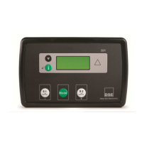
Describes the controls on the DSE7210/7310 autostart module.
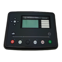
Describes the controls on the DSE7220/7320 AMF module.
Details the function of each control button on the module.
Explains how the module operates automatically.
Explains how the module operates manually.
Explains how to operate the module in Test mode.
Lists and describes shutdown conditions that stop the engine.
Continues the list and description of shutdown conditions.
Lists and describes electrical trip conditions that stop the generator.
Details the overcurrent protection features.
Continues the explanation of overcurrent protection settings and curves.
Details the earth fault protection features and IDMT curve.
Details the short circuit protection features and IDMT curve.
Essential checks before starting the system.
Continues the troubleshooting guide with more symptoms and remedies.
| Model | DSE7310 |
|---|---|
| Type | Auto Start Control Module |
| DC Supply | 8 V to 35 V continuous |
| Generator & Mains (Utility) Frequency | 3.5 Hz to 75 Hz |
| Storage Temperature Range | -40°C to +85°C |
| Communication Ports | RS232, RS485 |
| Cranking Dropouts | Able to survive 0 V for 50 mS, providing supply was at least 10 V before dropout and supply recovers to 5 V. This is achieved without the need for internal batteries. |
| Max. Standby Current | 80 mA at 24 V |
| Magnetic Pick-up Voltage Range | 0.5 V to 70 V |
| Magnetic Pick-up Frequency | 10, 000 Hz (max) |
| Display | pixel LCD |
| Protection Class | IP65 (front panel when installed) |