Do you have a question about the DSE DSE5510 and is the answer not in the manual?
Explains how the module starts and runs the generator automatically based on external signals.
Describes manual control of generator operations for testing and diagnostics.
Explains how alarms are indicated and displayed on the LCD.
Details non-critical alarm conditions that alert the operator to undesirable states.
Describes pre-alarm conditions that warn of potential future serious issues.
Details critical shutdown conditions that stop the generator and require fault rectification.
Explains latching electrical trips that stop the generator in a controlled manner.
Lists adjustable parameters in the main configuration editor with default values.
Lists adjustable parameters in the application editor with default values.
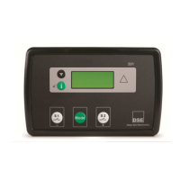
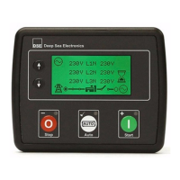
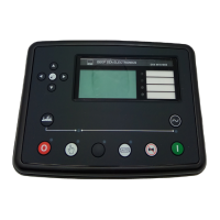
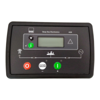
Explains the function of each push-button on the module.
Details module connections via plugs and sockets.
Outlines essential pre-start checks and the commissioning process.
Provides a guide to common symptoms and possible remedies for faults.
Shows wiring connections for a 3 CT system.
Shows wiring connections for a 4 CT system.
| Model | DSE5510 |
|---|---|
| Max. Operating Current | 340 mA at 12 V, 160 mA at 24 V |
| Max. Standby Current | 160 mA at 12 V, 80 mA at 24 V |
| Magnetic Input Frequency | 10, 000 Hz (max) |
| Operating Temperature Range | -30°C to +70°C |
| Storage Temperature Range | -40°C to +85°C |
| Type | Auto Start Control Module |
| Display | LCD |
| Input Voltage | 8 V to 35 V DC |
| Cranking Dropouts | Able to survive 0 V for 50 ms providing the supply was at least 10 V before dropout and recovers to 5 V afterwards |
| Alternator Input Range | 15 V AC (Ph-N) |
| Magnetic Input Range | 0.5 V to 70 V |
| Operating Temperature | +70°C |
| Protection Class | IP65 |