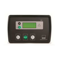
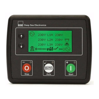
DSE Model 5510 Autostart Control and Instrumentation System Operators Manual
057-015 5510 OPERATING MANUAL ISSUE 11 07/07/09 AM 5
2 INTRODUCTION
The DSE 5510 Module allows the OEM to meet demand for increased capability within the industry.
It allows the user to start and stop the generator and if required, transfer the load to the generator
either manually or automatically. The user also has the facility to view the system operating
parameters via the LCD display.
Utilising the inbuilt synchronising, volts matching and paralleling functions, the controller is able to
parallel with the mains supply for simple peak lopping (fixed generator output). Alternatively, the
5510 can be used to parallel with other DSE 5510 load sharing controllers. Up to 16 sets can be
connected in paralleling and load share as a standalone (prime power) system. Additionally they can
parallel with the mains supply (when used in conjunction with DSE 5560).
The DSE 5510 module also monitors the engine, indicating the operational status and fault
conditions, automatically shutting down the engine. Exact failure mode information is indicated by the
LCD display on the front panel.
The powerful Microprocessor contained within the module allows for many features to be
incorporated as standard;
• Full Multilingual LCD display (including non-western character fonts).
• True R.M.S. voltage monitoring.
• Power measurement.
• Communications capability (RS485 or RS232 including GSM/SMS functions)
• Check Sync capability
• Automatic Sync capability
• Load share / control capability
• Fully configurable inputs for use as alarms or a range of different functions also available on
P130 expansion inputs (optional)
• Extensive range of output functions using built in relay outputs or relay expansion available.
• Instrumentation and diagnostics from electronic engines when connected to an engine ECU.
Selective operational sequences, timers and alarm trips can be altered by the customer via a PC
using the 5xxx For Windows ™ software and 810 interface or via the integral front panel
configuration editor.
Access to critical operational sequences and timers for use by qualified engineers, can be protected
by a security code. Module access can also be protected by PIN code. Selected parameters can be
changed from the module’s front panel.
The module is housed in a robust plastic case suitable for panel mounting. Connections to the
module are via locking plug and sockets.
http://bestgenerator.spb.ru/?page_id=6765