Do you have a question about the DSE DSE331 and is the answer not in the manual?
Defines the part numbering scheme for the DSE331 controller.
Covers power supply, voltage, frequency sensing, inputs, and outputs.
Details dimensions, mounting, applicable standards, and enclosure classifications.
Explains terminal functions and provides a typical wiring diagram for setup.
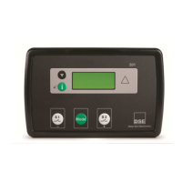
Identifies and describes the physical controls and display elements on the module.
Details mode selection, display pages, and quickstart guide for operation.
Describes automatic and manual operation, including sequences and load switching.
Details test mode operation and various load switching control schemes and timing.
Lists shutdown conditions, warnings, and alarms for S1 and S2 supplies.
Describes warning conditions for the plant battery voltage.
Procedure to access and edit parameters via the front panel editor.
Lists all configurable parameters for the module and application.
Information on ordering parts, fixing clips, gaskets, and warranty details.
Provides guidelines for disposal of electronic equipment according to WEEE and RoHS directives.
Explains how to connect the controller to a PC for configuration using DSE software.
| Cranking Dropouts | Able to survive 0 V for 50 mS, providing supply was at least 10 V before dropout and supply recovers to 5 V. This is achieved without the need for internal batteries. |
|---|---|
| Magnetic Input Frequency | 10, 000 Hz (max) |
| Operating Temperature Range | -40 °C to +85 °C |
| Storage Temperature Range | -40 °C to +85 °C |
| DC Supply | 8 V to 35 V |
| Max. Standby Current | 50 mA at 12 V |
| Alternator Input Range | 15 V |
| Alternator Input Frequency | 50 Hz - 60 Hz |
| Magnetic Input Range | 0.5 V to 70 V Peak |
| Protection Class | IP65 (Front only) |
| Dimensions | 72 mm x 72 mm |