Bibliography / Introduction
5
1 BIBLIOGRAPHY
This document refers to and is referred to by the following DSE publications which can be obtained from the DSE
website www.deepseaplc.com
DSE PART DESCRIPTION
053-131 DSE331 installation instructions
057-149 DSE331 Configuration Suite manual
2 INTRODUCTION
This document details the installation and operation requirements of the DSE331 Series modules, part of the
DSEAts ® range of products.
The manual forms part of the product and should be kept for the entire life of the product. If the product is passed
or supplied to another party, ensure that this document is passed to them for reference purposes.
This is not a controlled document. You will not be automatically informed of updates. Any future updates of this
document will be included on the DSE website at www.deepseaplc.com
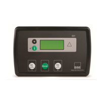
The DSE 331 module has been designed to allow the operator to control the transfer of the load from one supply
to another, typically the mains supply and a standby generator or two mains supplies.
The user also has the facility to view the system operating parameters via the LCD display.
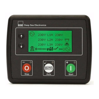
The DSE 331 module monitors the supplies, indicating the operational status and fault conditions, automatically
transferring the load to the backup supply in case of mains supply failure. The LCD display indicates the status.
The powerful microprocessor contained within the module allows for incorporation of a range of enhanced
features:
• Text & Icon based LCD display (selectable in the software)
• True RMS Voltage monitoring.
• Supply parameter monitoring.
• Fully configurable inputs for use as alarms or a range of different functions.
Using a PC and the DSE Configuration Suite software allows alteration of selected operational sequences, timers
and alarm trips.
Additionally, the module’s integral fascia configuration editor allows adjustment of this information.
A robust plastic case designed for front panel mounting houses the module. Connections are via locking plug and
sockets.