DSE Model 5510 Autostart Control and Instrumentation System Operators Manual
057-015 5510 OPERATING MANUAL ISSUE 11 07/07/09 AM 48
9 ELECTRICAL CONNECTIONS
Connections to the Module are via plug and sockets.
9.1 CONNECTION DETAILS
The following describes the connections and recommended cable sizes to the 8 plugs and sockets
on the rear of the Module.
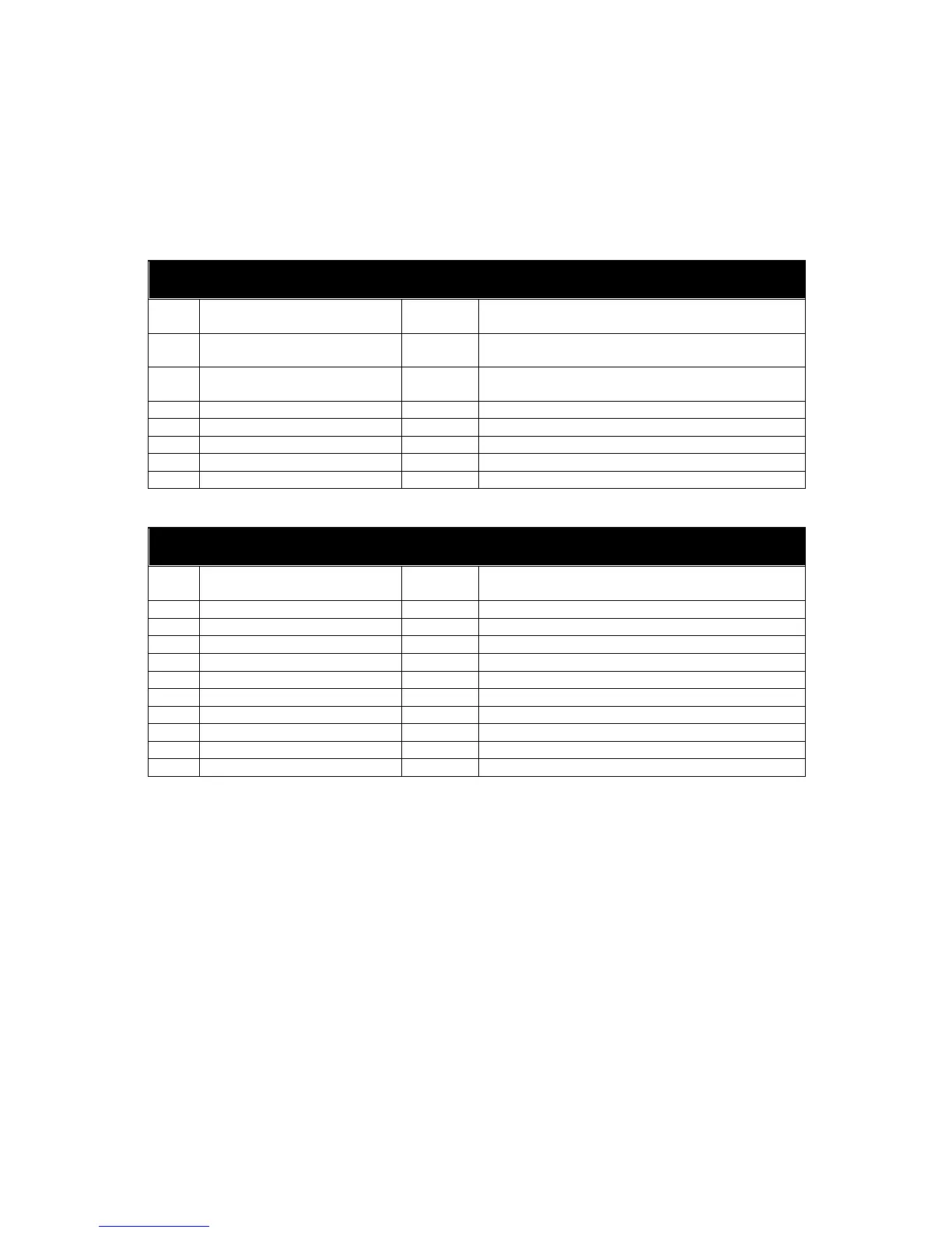
9.1.1 PLUG “A” 8 WAY
PIN
No
DESCRIPTION CABLE
SIZE
NOTES
1 DC Plant Supply Input
Negative
2.5mm
2 DC Plant Supply Input
Positive
2.5mm (Recommended Fuse 20A Max.)
3 Emergency Stop Input 2.5mm Plant Supply positive. Also supplies fuel & start
outputs. (Recommended Fuse 32A Max.)
4 Fuel relay Output 2.5mm Plant Supply positive from pin 3. 16 Amp rated.
5 Start relay Output 2.5mm Plant Supply positive from pin 3. 16 Amp rated.
6 Auxiliary Output relay 1 1.0mm Plant Supply positive, 5 Amp rated.
7 Auxiliary Output relay 2 1.0mm Plant Supply positive, 5 Amp rated.
8 Auxiliary Output relay 3 1.0mm Plant Supply positive, 5 Amp rated.
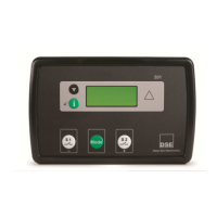
9.1.2 PLUG “B” 11 WAY
PIN
No
DESCRIPTION CABLE
SIZE
NOTES
9 Charge Fail Input/ Excitation
Output
1.0mm Must NOT be connected to plant supply negative
10 Auxiliary Input 1 0.5mm Switch to plant supply negative
11 Auxiliary Input 2 0.5mm Switch to plant supply negative
12 Auxiliary Input 3 0.5mm Switch to plant supply negative
13 Auxiliary Input 4 0.5mm Switch to plant supply negative
14 Auxiliary Input 5 0.5mm Switch to plant supply negative
15 Auxiliary Input 6 0.5mm Switch to plant supply negative
16 Auxiliary Input 7 0.5mm Switch to plant supply negative
17 Auxiliary Input 8 0.5mm Switch to plant supply negative
18 Auxiliary Input 9 0.5mm Switch to plant supply negative
19 Functional Earth 2.5mm Connect to system earth