DSE Model 5510 Autostart Control and Instrumentation System Operators Manual
057-015 5510 OPERATING MANUAL ISSUE 11 07/07/09 AM 71
uninterruptible power supply arrangement is recommended (AC or DC depending on modem
power requirement).
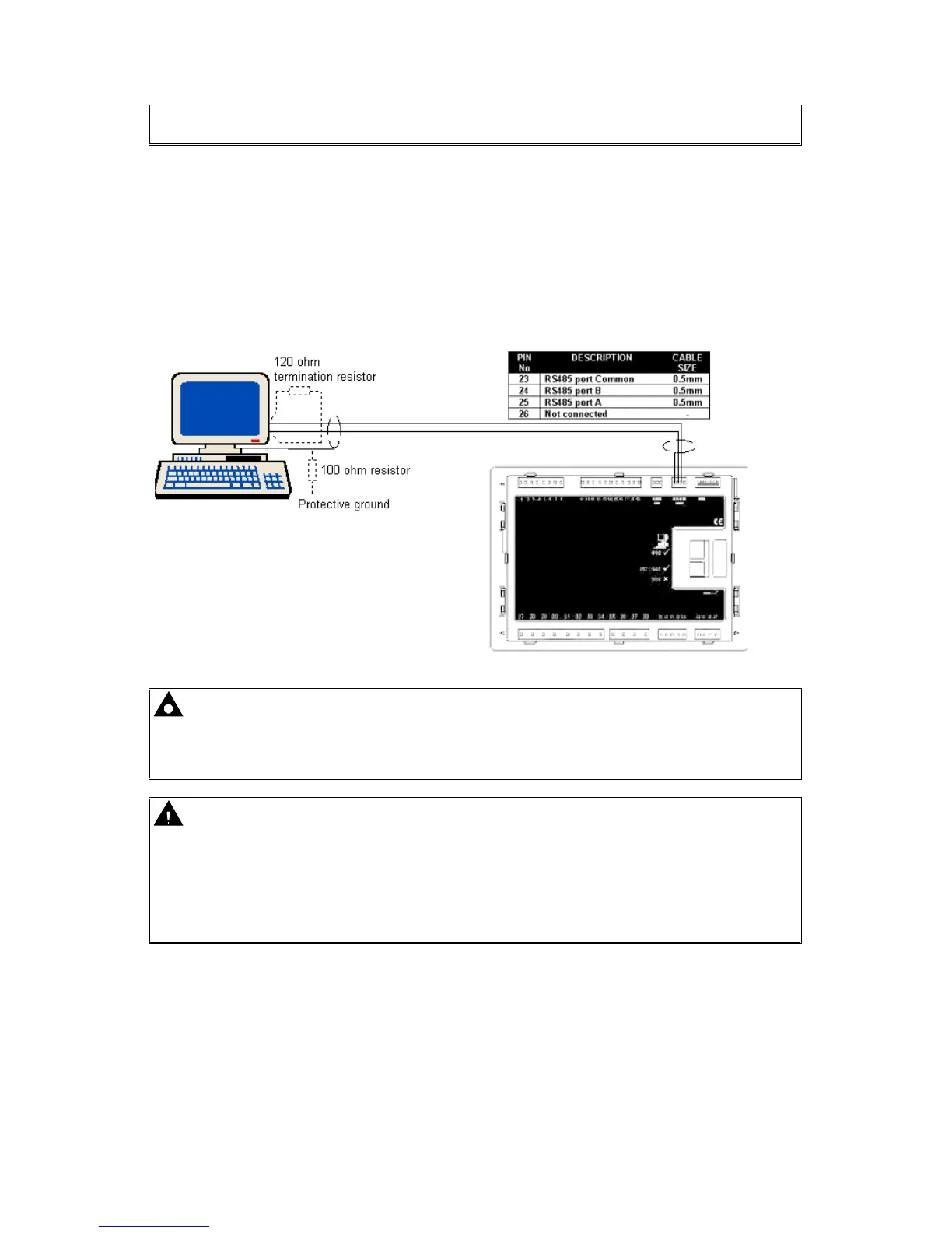
16.4.4 RS485 LINK TO CONTROLLER
The RS485 enabled 5510 modules are able to communicate with a PC or other RS485 enabled
device over a standard RS485 connection. Typical uses of RS485 are:
• Direct connection to a remote PC running the Link5000 software. RS485 is capable of
communication over a distance of 1.2km where suitable 120Ω RS485 cable is installed.
• Connection to a building management to allow mains, generator and engine parameters/alarm
conditions to be displayed along with information from other devices (air conditioning, fire alarm
system etc).
NOTE: - The RS485 system will comprise of one MODBUS master (typically a PC) and
up to 31 MODBUS slaves. The 5510 modules are always MODBUS slave devices. To ensure
correct operation a suitable 120Ω
ΩΩ
Ω terminal resistor must be fitted to each end of the RS485
connection bus.
Caution! - The A and B lines of the 485 network should be terminated at each end with a
120Ω
ΩΩ
Ω resistor.
Some RS485 devices (PC cards in particular) are already fitted with a terminating resistor.
However if they are not installed as an ‘end of line’ device then such terminating resistors
must be removed. Other RS485 devices may be fitted with a ‘switchable’ resistor, again this
must be switched out if the device is not installed as an ‘end of line’ device.
Typical connections of
RS485 PC system
(master) to RS485 DSE
controller (slave)