3
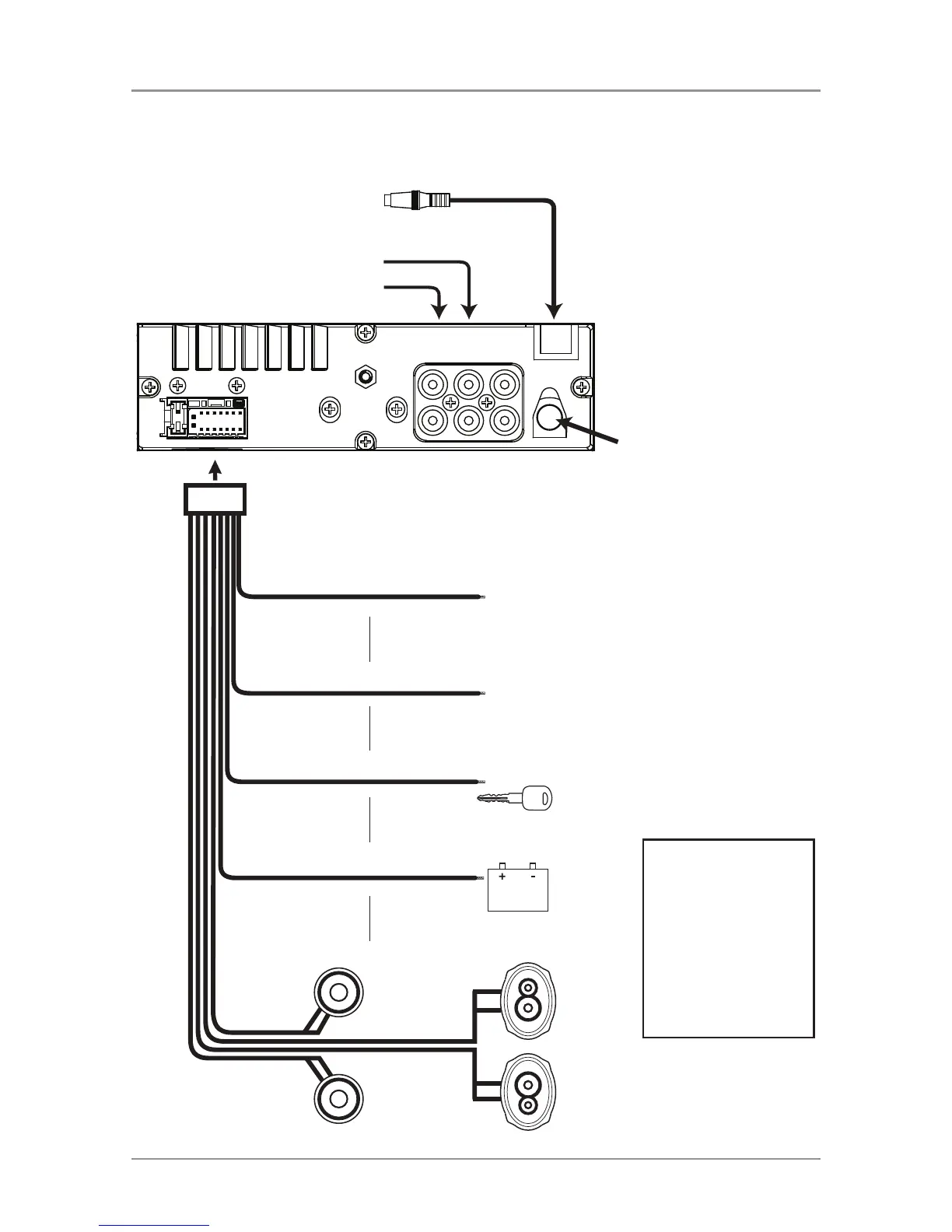
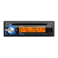
DC535Bi
BLUE
BLACK
RED
YELLOW
Remote Turn-On
Connect to amplifier or power
antenna. Insulate wire if not used.
Ground
Connect to the vehicle
chassis ground.
Accessory
Connect to an existing ignition
circuit or switched 12 volt source.
Memory
Connect to the battery
circuit or constant 12 volt source.
Right Front
Gray/Black (-)
Gray (+)
Left Front
White/Black (-)
White (+)
Left Rear
Green/Black (-)
Green (+)
Right Rear
Violet/Black (-)
Violet (+)
SUBREARFRONT
L-CH
R-CH
Antenna
Connector
Rear Output
Front Output
Subwoofer Output
Steering Wheel
FUSE
When replacing the fuse,
make sure new fuse is the
correct type and amperage.
Using an incorrect fuse could
damage the radio.
The DC535Bi uses one
10 amp ATM fuse located
in-line.
Wiring Diagram