ISO 9001: 2015
TCDS EASA: EASA P.038
Part 21G EASA: FR.21G.0273
7/27
4. Components of the Certified FLASH-R
Mounting configuration of the FLASH-R propeller 4.1.
Here is a configuration table of the three-blade certified FLASH-R propeller mounting according the propeller-shaft of
the engine.
If needed, see annex 9.1 Dimension of the engine propeller-shaft
Type SAE1
Ø4-3/8" / Ø111.125mm
(Ex: Continental O-200)
Type SAE2
Ø4-3/4" / Ø120.65mm
(Ex: Lycoming O-320)
direct on propeller-
shaft (without spacer)
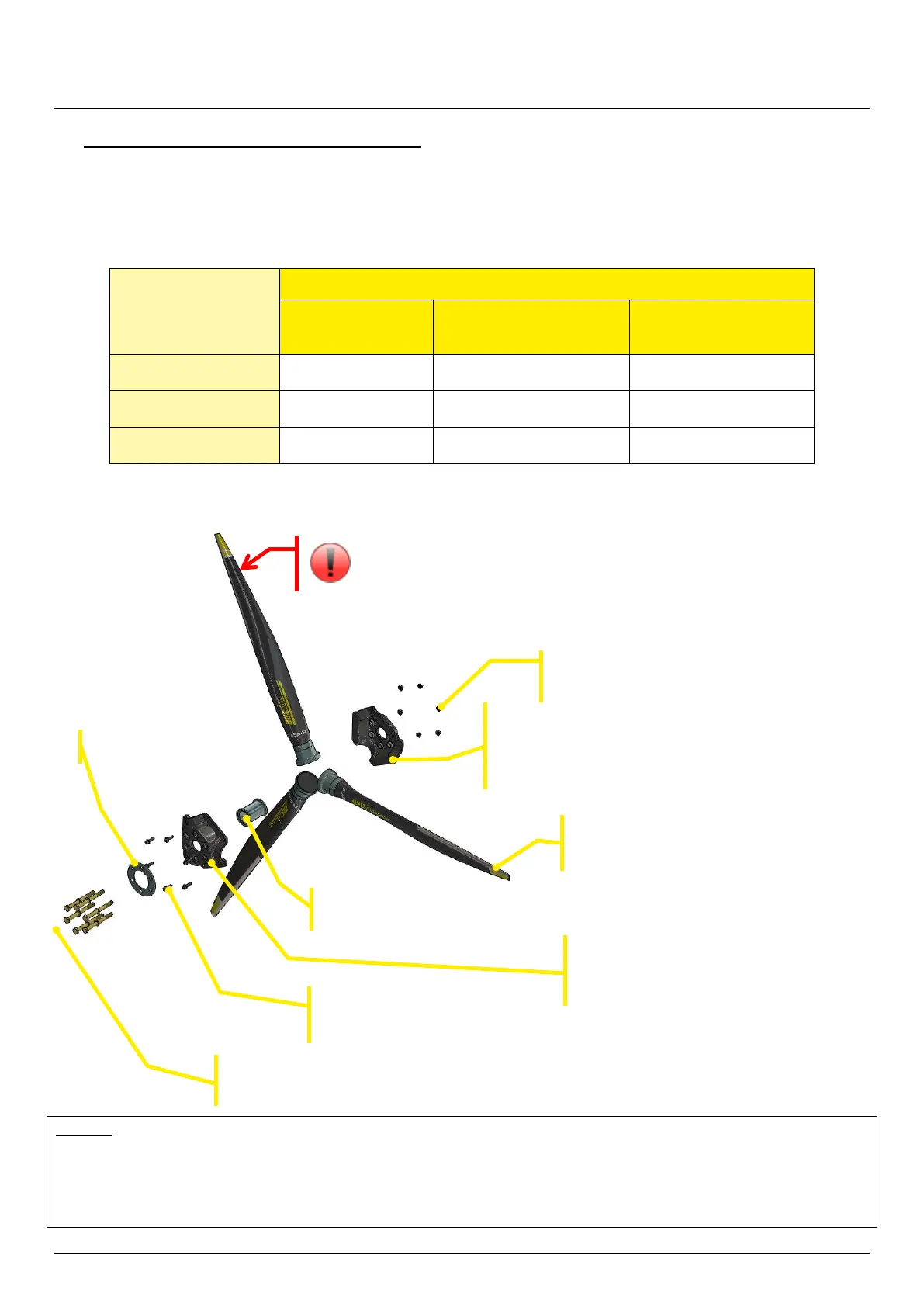
Exploded view for propeller 4.2.
Remark
This exploded view shows the principle of the certified FLASH-R propeller assembly. The size of all of these
components changes depending on the configuration of the propeller (diameter hole of the metallic inserts of the half-
hub, length of the screws…).
Inconel FLASH-R
blade right(x3)
Screws & washers
for hub assembly (x6)
Locking nuts & washers
for hub assembly (x6)
Rear half-hub (x1)
with rear metallic inserts (x6)
According to mounting
Fixing screws and washers of the propeller
adapted according the mounting (x6)
Caution when handling the blades
CUTTING TRAILING EDGE
Front half-hub (x1)
with front metallic inserts (x6)
According to mounting