Certified FLASH-R
10/27
List of required tools 4.4.
SAE1/SAE2 mounting (Lycoming, Continental, …)
6 Torque Allen Wrench (Torque: 25 Nm)
Flat key 13
Inclinometer (angle adjustment tools)
Nylon mallet
Torque screwdriver (Torque: 4 Nm)
6 Torque Allen Wrench (Torque: 25 Nm)
Flat key 13
3/8 or 1/2 Torque Wrench (Torque: 30 to 45 Nm)
Inclinometer (angle adjustment tools)
Nylon mallet
Torque screwdriver (Torque: 4 Nm)
5. Assembly instruction of the propeller
The assembly of the Three-blade Certified FLASH-R propellers is shown below. It is recommended to assemble the
propeller on a worktable before installing it on the plane.
For further information, contact the DUC Hélices Company.
Assembly of the propeller 5.1.
A « Propeller Form » will be done to insure a propeller follow-up. Parts Number and component serial number of
propeller will be written on this form.
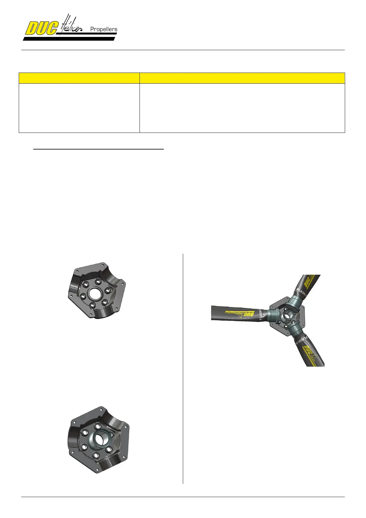
STEP
Place the rear half-hub on a worktable.
Be careful not to invert with the front hub half.
Depending on your installation, the rear half-hub is one
mounted on the propeller-shaft of the engine or on a
spacer. The diameter of the bore of the metal inserts of
the rear half- hub is larger than the bore of the metal
inserts of the front half-hub.
STEP
Place the hub spacer in the center of the rear half-hub.
STEP
Positioning the blades in their hub slots by placing them
outwards.
The three blades of the propeller have been
balanced at DUC Helices before their dispatch.
Position the DUC Hélices logo facing you.
Note that the metal inserts of the half-hub allow a
locking of the blades in their axis within the hub.