A
B
C
D
E
F
G
H
L
M
N
P
Comandi - Dispositivi
Controls - Devices
sezione / section
F 2
12 Monster 400/620 - M.Y. 2004 - edizione/edition 00
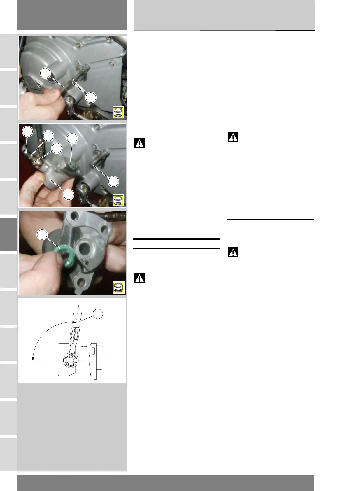
Rimontaggio gruppo
rinvio frizione
Lubrificare e riposizionare l’asta di
rinvio frizione (16) con i due anelli OR
(17).
Lubrificare la guarnizione (13) e
posizionarla con il gruppo rinvio (14)
sul carter.
Serrare le viti (15) alla coppia
prescritta (Sez. C 3).
Posizionare il tubo (6) sul gruppo
rinvio frizione (14), facendo
attenzione all’orientamento del
raccordo del tubo sul gruppo (14).
Attenzione
Un posizionamento non
corretto può causare mal
funzionamenti dell’impianto e può
interferire con le parti in movimento
del motociclo.
Posizionare le due guarnizioni (8) e
serrare la vite (10) alla coppia
preserrata (sez. C 3).
Rimontare lo spurgo (11) e il
parapolvere (12).
Posizionare delle fascette che fissano
il tubo (6), fare riferimento alla tavola
della pagina seguente.
Attenzione
Nel rimontaggio lubrificare la
guarnizione OR (13) e l’asta di rinvio
(16).
Operazioni Rif. Sez.
Riempire l’impianto
frizione
D 4
Refitting the clutch
transmission assembly
Lubricate and refit the clutch pushrod
(16) with both O-rings (17).
Lubricate the seal (13) and fit with the
transmission unit (14) onto the
casing.
Tighten the screws (15) to the
specified torque (Sect. C 3).
Position the hose (6) onto the clutch
transmission unit (14). Ensure the
hose fitting is properly positioned
onto the unit (14).
Warning
Incorrectly positioned hoses
can cause faults and interfere with
moving parts.
Position both seals (8) and tighten
screw (10) to the specified torque
(Sect. C 3).
Refit the drain (11) and the dust seal
(12).
Please refer to the table on next page
for proper positioning of clamps for
hose (6).
Warning
Lubricate the O-ring (13) and
the pushrod (16) before reassembly.
Operations Ref.Sect.
Fill the clutch circuit D 4
16
17
B
13
16
B
12
11
10
14
13
B
100˚
96˚
6