Do you have a question about the Ducati MONSTER 695 and is the answer not in the manual?
Explains the manual's structure in sections, chapters, and paragraphs.
Explains how to interpret numerical references to parts in text and figures.
Details threadlocker, sealant, and lubricant specifications with corresponding symbols.
Provides fundamental safety advice for handling hazardous materials and operations.
Details VIN structure for European and USA versions, including model year and plant of manufacture.
Explains the identification data format for the engine, including type and serial number.
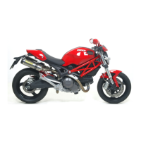
Lists key physical dimensions of the motorcycle including length, width, wheelbase, and seat height.
Details frame type, steering angles, trail, and rim specifications.
Provides engine type, bore, stroke, displacement, compression ratio, power, and torque specifications.
Details clutch, gearbox, primary drive, transmission ratio, final drive, and gear ratios.
Lists standard and service limit values for gearbox shafts, drum, and selector fork clearances.
Details front fork type, travel, clevis pin, and oil quantity per leg.
Lists minimum tread thickness, tyre pressure, swingarm shaft eccentricity, and wheel rim specifications.
Details battery voltage, charge, type, and generator capacity.
Specifies fuel type, throttle body diameter, and number of injectors.
Specifies fuel type and tank capacity, including reserve.
Recommends using highly detergent engine oil with specific certifications for optimal engine properties.
Lists torque values for various frame components like chain, sprockets, and light units.
Provides torque specifications for rear brake caliper, master cylinder, and hose clips.
Specifies torque values for mudguard retaining screws and protection screws.
Provides torque specifications for engine components like blow-by valve, oil filter, and wet clutch drum nut.
Lists specific tools for engine work, including belt roller ring nut tool and timing belt tensioner.
Provides guidelines for engine break-in, including RPM limits and driving recommendations.
Details how to check engine oil level via sight glass and topping up if necessary.
Provides step-by-step instructions for starting the engine in cold ambient conditions.
Outlines periodic maintenance tasks for dealers based on mileage or time intervals.
Lists basic maintenance tasks for the owner to perform at set intervals.
Details how to check the engine oil level using the sight glass and topping up if required.
Provides instructions for draining old oil, replacing the filter cartridge, and refilling with new oil.
Explains how to measure valve clearances for intake and exhaust using feeler gauges.
Guides on replacing or cleaning the air filter at specified intervals for optimal engine performance.
Provides instructions for changing brake fluid, including warnings about spills and safety precautions.
Details the procedure for filling the front brake circuit with fresh fluid and bleeding the system.
Explains how to drain the hydraulic braking system, emphasizing safety precautions for brake fluid.
Guides on filling the brake circuit with specified fluid, ensuring proper topping up and air removal.
Provides instructions for changing clutch fluid, including safety warnings related to clutch fluid.
Instructs on using a suction method to remove oil from the reservoir.
Details how to let oil flow from the bleed valve until a different color is observed.
Explains how to drain the clutch circuit, including safety warnings for clutch fluid.
Describes how to push the piston to expel all fluid from the unit.
Instructs to operate the clutch lever multiple times to reach all circuit points and expel any air.
Details how to adjust steering head bearings to eliminate play and ensure proper steering.
Guides on adjusting chain tension by finding the tightest position and adjusting nuts.
Explains how to check brake pad wear and provides instructions for changing the pads.
Provides step-by-step instructions for changing brake pads, including removing split pins and retaining pins.
Instructs on checking rear brake pad wear through the caliper slot for minimum friction material.
Explains how to adjust throttle and choke cables for proper operation and mentions potential impact on throttle body adjustments.
Describes how to make fine adjustments to the throttle cable using the adjuster on the handlebar.
Details how to adjust rear shock absorber settings for rebound damping and spring preload.
Details the DDS base unit, its components, and its function in diagnosing injection-ignition systems.
Describes the DDS diagnostic system, its features for testing motorcycle devices, and measurement capabilities.
Explains how to power the DDS instrument using mains or vehicle battery.
Provides instructions on connecting the DDS to the motorcycle battery, ensuring correct voltage supply.
Outlines the functions of the DDS, including error reading, parameter reading, and active diagnosis.
Details the procedure for checking and adjusting timing belt tension using the DDS and related tools.
Guides on resetting the throttle position sensor for proper system operation after component replacement.
Explains how to adjust idle speed and CO level using bypass screws and a gas analyser.
Describes how to adjust the choke control lever for smooth operation.
Details how to take oil circuit pressure readings using the DDS and pressure sensor.
Provides test values for oil pressure at different RPMs and warns about maximum pressure limits.
Explains the importance of compression and how to check it, noting factors affecting performance.
Details connecting the cylinder compression cable to the spark plug hole and pressure sensor.
Instructs to crank the engine with the starter motor until pressure reading stops rising for compression check.
Guides on checking fuel pressure by connecting a pressure sensor to the fuel delivery hose.
Details connecting the pressure sensor to specific ports on the cable for measurement.
Explains how measured values can be displayed as numbers or graphs on the DDS.
Provides emergency steps to start the engine if the immobilizer is faulty.
Guides on navigating the DDS menu to select vehicle model, version, and enter self-diagnosis.
Instructs to press 'Actuators' to view connected ECU components for diagnosis.
Explains how the DDS guides the operator through diagnosis stages and provides component information.
Guides on selecting the vehicle model and version within the DDS for diagnosis.
Instructs to use the 'Step-by-step diagnosis' function for detailed diagnostic procedures.
Explains that DDS queries ECU and displays elements with their values.
Explains how to check the charging system using the DDS and an ammeter clamp.
Details connecting the ammeter clamp to the DDS power and diagnosis cable for current measurement.
Warns about reversed polarity affecting ammeter readings and leading to wrong diagnosis.
Covers essential pre-ride checks for safe operation, including fluid levels and controls.
Provides step-by-step instructions for starting the engine in cold ambient conditions.
Outlines periodic maintenance tasks for dealers based on mileage or time intervals.
Covers various maintenance tasks like oil changes, valve clearance checks, and filter replacement.
Details diagnostic tools like DDS and multimeters for checking electrical systems.
Explains the disassembly and refitting procedure for rear-view mirrors.
Covers seat removal, refitting, splash guard, and side body panel procedures.
Details removal and refitting procedures for front and rear mudguards.
Details throttle and choke cable adjustments, disassembly, and reassembly.
Covers clutch master cylinder and transmission unit removal and refitting.
Explains removal and refitting of the front brake master cylinder and system.
Covers rear brake system removal and refitting, including master cylinder and caliper.
Details removal, disassembly, and refitting of the gear change control mechanism.
Explains removal and refitting of the seat lock and releasing mechanism.
Covers front wheel removal, overhauling, and refitting procedures.
Details front fork removal, overhauling, and refitting procedures.
Covers braking system maintenance, removal, and refitting of front brake system components.
Covers rear wheel removal, overhauling, and refitting procedures.
Details swingarm removal, inspection, and refitting procedures.
Covers rear brake system removal and refitting, including caliper and hose connections.
Details rear suspension components and overhaul procedures for shock absorber and rocker arm.
Covers final drive inspection, chain sprocket removal, and refitting.
Explains the removal and refitting procedures for the motorcycle handlebar.
Details steering bearing play adjustment and steering tube disassembly/refitting.
Covers removal and refitting procedures for footpegs and footpeg plates.
Guides on removing and refitting the side stand.
Explains how to check frame dimensions and handle damaged frames.
Details removal and refitting of the tail light and number plate holder.
Describes the fuel system, including the plastic fuel tank, throttle body, airbox, and exhaust.
Details throttle body removal, refitting, and injector procedures.
Covers airbox removal, filter element replacement, and refitting procedures.
Explains catalytic converter operation, precautions, and removal/refitting of the exhaust system.
Details the Canister Filter System for USA versions, including removal and refitting.
Provides general information on the fuel injection-ignition system and its circuits.
Lists components of the injection-ignition system.
Describes ECU, sensors, injectors, coils, and spark plugs.
Covers engine removal and reassembly procedures, referencing other sections.
Details oil pump components, operation, removal, disassembly, and reassembly.
Covers removal and refitting of the oil breather tank and valve.
Details checks and adjustments for valve clearance, engine timing, and camshafts.
Covers removal, disassembly, and reassembly of timing side covers and system.
Details removal, overhaul, and refitting of camshafts, including checking bearings and oil seals.
Covers disassembly and reassembly of valves, rocker arms, and related components.
Details removal, overhauling, and refitting of cylinder and piston assembly.
Describes APTC wet clutch unit, its advantages, and disassembly/reassembly procedures.
Covers removal, disassembly, and refitting of the clutch cover.
Details disassembly and refitting of primary drive gears and checking meshing play.
Covers removal, disassembly, and refitting of gear selector levers.
Details gearbox shaft removal, disassembly, overhauling, and reassembly.
Covers generator cover, flywheel, and rotor removal, disassembly, and reassembly.
Details removal and refitting of outer components like engine, lubrication system, and head unit.
Covers opening, overhauling, shimming, and closing crankcases.
Details removal, disassembly, overhauling, and reassembly of connecting rods.
Lists electrical components of the wiring system with reference numbers.
Provides wire color codes used in the wiring diagram.
Explains the legend for the fuse box positions, descriptions, and ratings.
Details the optimized routing of wiring on the frame to ensure minimum obstruction.
Shows the wiring harness routing from the ignition switch to various components.
Illustrates connections related to the ignition switch and handlebar controls.
Shows wiring connections for the engine control unit and related sensors.
Illustrates wiring connections for the regulator and its components.
Shows wiring connections for the throttle body, injectors, and position sensor.
Illustrates wiring connections for the engine control unit and related components.
Shows wiring connections for the neutral switch, stop switches, and instrument panel.
Illustrates wiring connections for turn indicators and lighting system components.
Shows wiring connections for the air temperature sensor.
Illustrates wiring connections for the headlight and related components.
Shows wiring connections for the side stand switch and related components.
Illustrates wiring connections for the headlight support and instrument panel.
Shows wiring connections for the speed sensor.
Explains how to check the charging system using the DDS tester and multimeter.
Provides instructions for recharging the battery, including charge types and safety precautions.
Guides on adding electrolyte to the battery, including safety warnings and precautions.
Details battery safety rules, instructions for use, and precautions.
Covers battery removal and refitting, including regulator fuse and ECU.
Describes the generator as a 12V, 520W alternator with stator and rotor.
Explains the function of the rectifier-regulator and its connection to the motorcycle frame.
Details key components of the electric starting system: starter contactor, motor, and ECU.
Describes the starter motor power, direction of rotation, and troubleshooting steps.
Guides on removing the starter motor by disconnecting cables and undoing retaining screws.
Details refitting the starter motor, including inspecting gasket and tightening screws.
Explains the starter contactor's connection to the frame and its operational check.
Provides instructions for changing headlight and number plate light bulbs.
Guides on removing and refitting the headlight assembly.
Details the location and function of the high beam relay and its strategy.
Explains the procedure for setting the headlight beam height against a wall.
Guides on checking components like switches and indicators for electric continuity.
Details checking the left switch for continuity and wire colors.
Explains how to check HORN button continuity using a multimeter.
Guides on checking turn indicator switch continuity using a multimeter.
Details checking the right switch for continuity and wire colors.
Explains how to check the engine stop switch continuity.
Guides on checking the starter button continuity using a multimeter.
Details checking the parking light/low beam switch continuity.
Explains how to check STOP switches for electric continuity.
Guides on checking the neutral light switch operation.
Details how to check the oil pressure sensor for proper operation using DDS.
Provides instructions for checking the clutch switch, similar to STOP switches.
Guides on replacing stop and parking light bulbs.
Guides on checking the key-operated switch for electric continuity in different positions.
Explains how to check the side stand switch operation using a multimeter.
Details checking fuses in the main fuse box and the regulator fuse.
Describes instrument panel operations, including LCD unit, clock setting, and light indicators.
Explains oil temperature warning indications (LO and HI).
Details the low fuel warning indication and trip fuel function.
Explains the maintenance warning display and how to cancel it.
Guides on setting the instrument panel light brightness.
Describes the system's strategy for automatic switch-off and reactivation of lights.
Describes the different types of keys (red and black) and their functions.
Provides step-by-step instructions for programming the immobilizer system.
Explains LED indications for programming status and troubleshooting faults.
Details the emergency procedure to start the engine if the immobilizer is faulty.
Guides on removing the immobilizer antenna and switch.
Details refitting the immobilizer antenna, switch, and related components.
Explains how to dismantle the red key and transponder.
Provides guidance on using multimeters for checking resistance, voltage, and current.
Details connecting multimeter terminals in parallel to measure voltage.
Explains connecting multimeter terminals in series to measure current.
Guides on measuring resistance and checking electric continuity.
Provides precautions for using the multimeter, including handling fuses and batteries.
| Displacement | 695 cc |
|---|---|
| Compression Ratio | 10.5:1 |
| Fuel System | Electronic fuel injection, 45 mm throttle body |
| Transmission | 6-speed |
| Frame | Tubular steel trellis frame |
| Front Brakes | 2 x 300 mm discs, 2-piston calipers |
| Rear Brakes | 245mm disc, 2-piston caliper |
| Seat Height | 770mm (30.3 in) |
| Engine Type | L-Twin, 2 valves per cylinder Desmodromic |
| Bore x Stroke | 88 mm x 57.2 mm |
| Power | 54 kW @ 8, 500 rpm |
| Torque | 68 Nm @ 7750 rpm |
| Front Suspension | 43 mm upside-down fork |
| Dry Weight | 165 kg |
| Fuel Capacity | 14 litres (3.7 US gal) |
| Rear Suspension | Progressive linkage with preload adjustable monoshock |