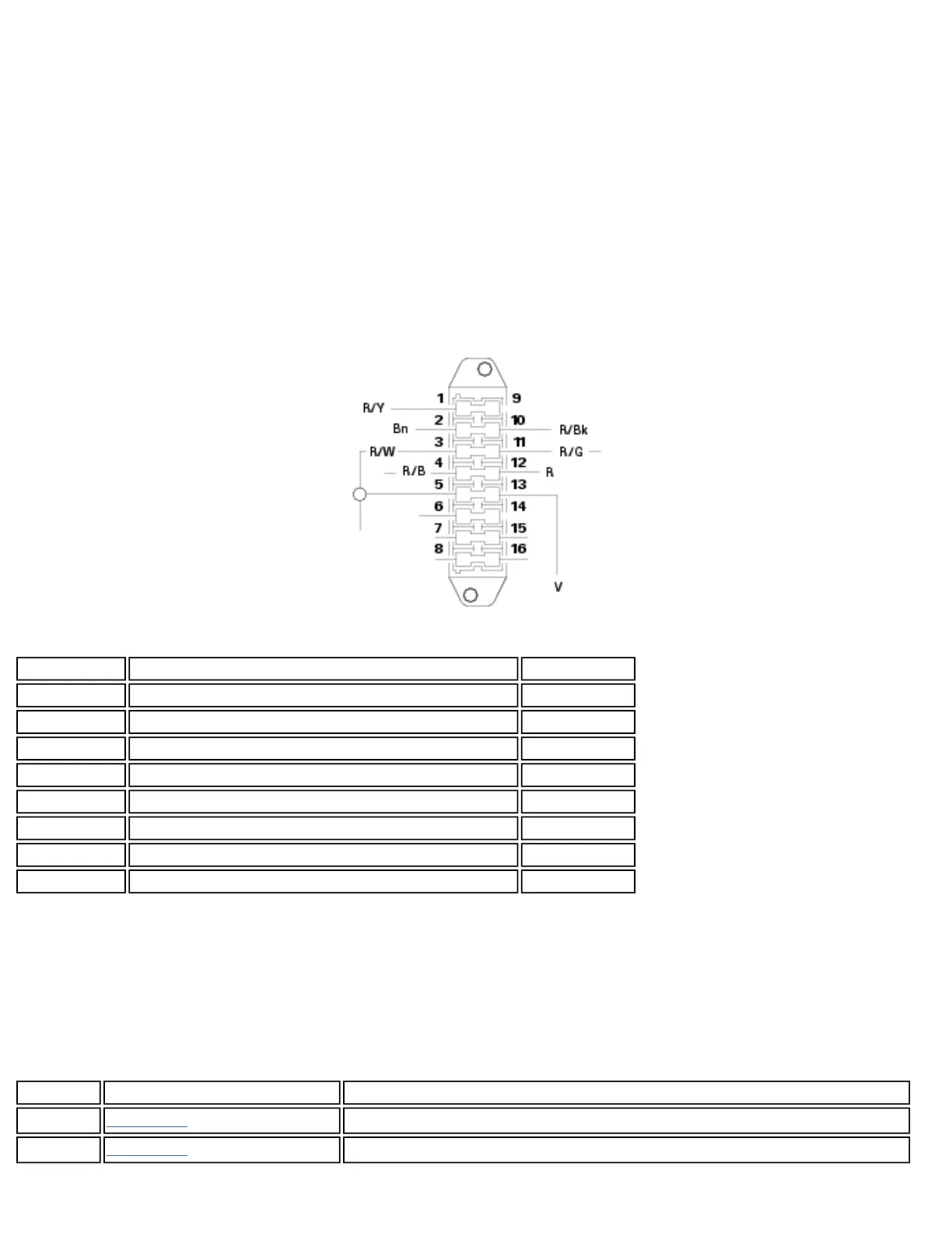
Wire color coding - wiring diagram
B Blue
Bk Black
Bn Brown
G Green
Gr Grey
Lb Light blue
O Orange
P Pink
R Red
V Violet
W White
Y Yellow
Legend of fuse box
Position Description Rating
1-9 Instrument panel 5A
2-10 Injection 20A
3-11 Key sense 10 A
4-12 Ecu 5A
5-13 Loads 15 A
6-14 Parking lights, high and low beam 15 A
7-15 Spare 20A
8-16 Spare 5A
Arrangement of wiring on frame
Routing of wiring has been optimized to ensure the minimum obstruction.
Each section is designed to prevent interference with parts that might damage wires or cause operating failures when
riding. The diagrams on the following pages show the origins (“0” points) for cables proper re-routing and cable ties
locations.
Each figure includes references to the diagrams showing the cable routing or the item it will have to be connected to.
Position
Description
1
Diagram A Horizontal injector connector
2
Diagram A Control unit oil temperature connector
file:///C|/Documents%20and%20Settings/F4i/My%...manual/wsm/usa/Mon695_MY07_P_1A9_00.77.1.html (3 of 5) [10/7/2008 8:46:49 PM]



 To Next Page