A
B
C
D
E
F
G
H
L
M
N
P
Ruote - Sospensioni - Freni
Wheels - Suspensions - Brakes
sezione / section
G 3
28 Monster 400 - 620 Aggiornamento/Update - M.Y. 2006 - edizione/edition 00
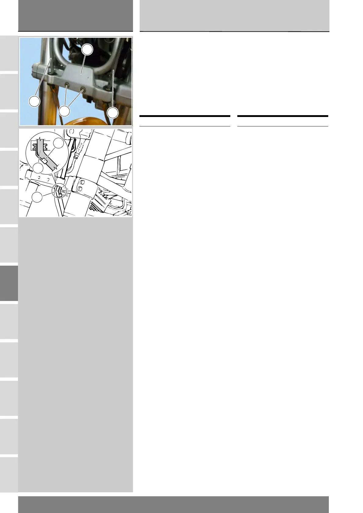
Inserire il tubo (8) nel supporto fanale
(15), facendo attenzione al
posizionamento del passacavo (12).
La sua forma piegata guida il
movimento del tubo (8) nella fase di
frenata, impedendogli spostamenti
irregolari.
Rispettare l’orientamento
rappresentanto in figura.
Serrare le viti (16) alla coppia
prescritta (Sez. C 3).
Operazioni Rif. Sez.
Riempimento impianto
frenante
D 4
Slide the hose (8) into the headlight
bracket (15). Thread the hose through
the hose guide (12).
The particular bent shape of the hose
guide is designed to restrict hose (8)
movement under braking and avoid
damage.
Correct position is shown in the
diagram.
Tighten the screws (16) to the
specified torque (Sect. C 3).
Operations Ref. Sect.
Fill the braking system D 4
16
15
8
8
12
12
8