Impianto iniezione - accensione
Injection - ignition system
sezione / section
M 1
5
A
B
C
D
E
F
G
H
L
M
N
P
Monster 400 - 620 Aggiornamento/Update - M.Y. 2006 - edizione/edition 00
Note
Per il controllo dei componenti
e dei relativi cablaggi dell'impianto
iniezione-accensione utilizzare lo
strumento di diagnosi “DDS”
seguendo le indicazioni riportate al
paragrafo “Diagnisi guidata” (Sez. D
5).
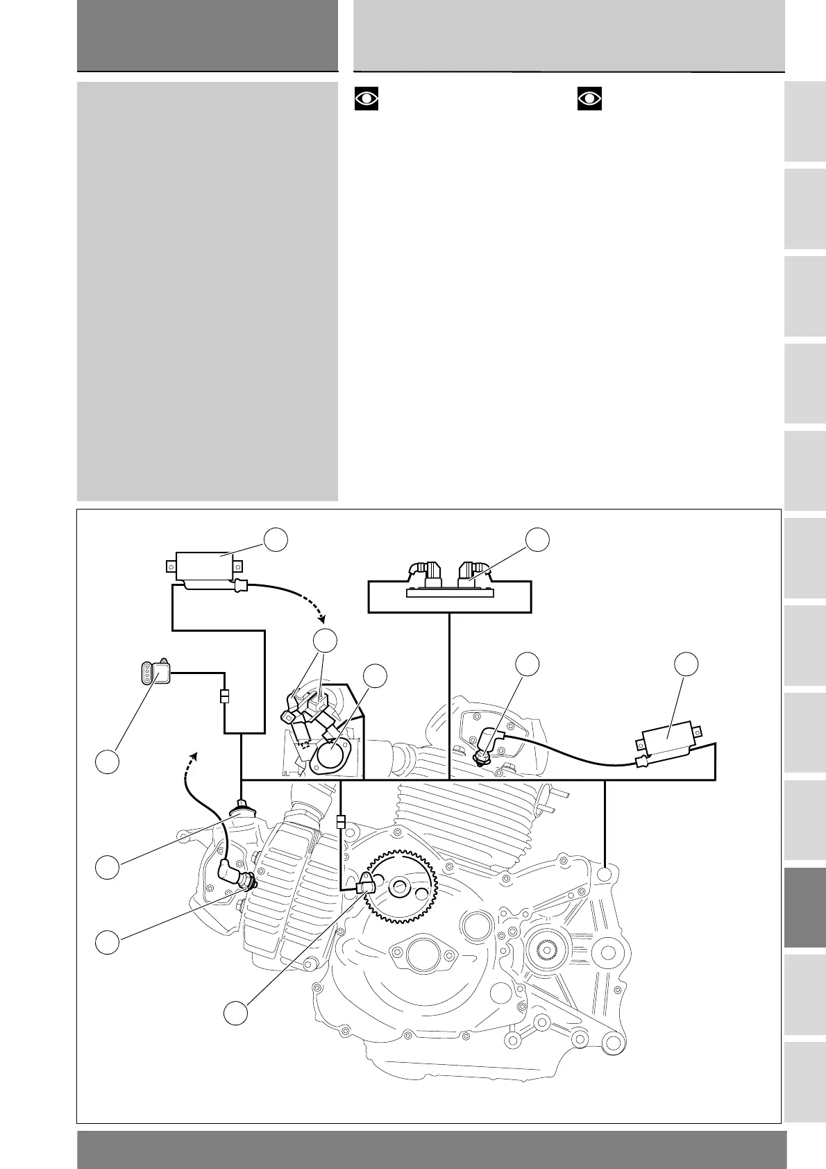
Legenda schema
posizionamento sensori
1 Bobina (cilindro orizzontale)
2 Centralina iniezioneBobina
(cilindro verticale)
3 Bobina (cilindro verticale)
4 Candela
5 Potenziometro farfalla
6 Iniettori
7 Sensore pressione - temperatura
aria
8 Sensore temperatura olio
9 Sensore giri motore
Note
For testing the components
and relative wiring of the injection-
ignition system, use the "DDS" tester,
following the indications under
"Guided diagnosis" (Sect. D 5).
Legend to sensor position
diagram
1 Coil (horizontal cylinder)
2 ECU Coil (vertical cylinder)
3 Coil (vertical cylinder)
4 Spark plug
5 Throttle position sensor
6 Injectors
7 Air pressure / temperature sensor
8 Oil temperature sensor
9 Engine rpm sensor
5
4
1 2
7
6
3
8
4
9