A
B
C
D
E
F
G
H
L
M
N
P
Impianto elettrico
Electric system
sezione / section
P 3
33Monster 400 - 620 Aggiornamento/Update - M.Y. 2006 - edizione/edition 00
Smontaggio motorino
avviamento
Rimuovere il coperchio alternatore
(Sez. N 8).
Nel caso in cui sia necessario
sostituire tutto il gruppo ingranaggi
avviamento, rimuovere gli ingranaggi
rinvio distribuzione e l’ingranaggio
rinvio motorino avviamento (Sez. N
9.1).
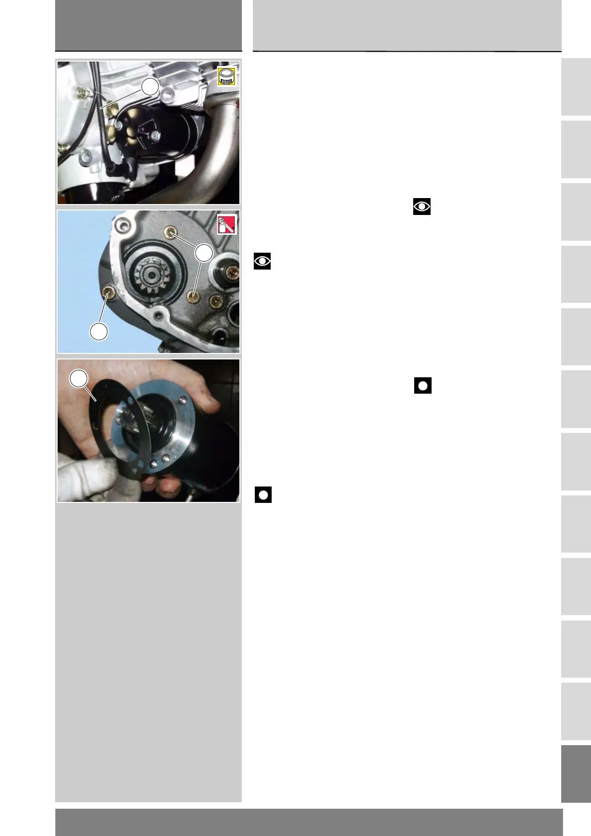
Scollegare il cavo motorino
avviamento / teleruttore (3) (fare
riferimento alla tavola al capitolo
“Disposizioni dei cablaggi sul
motociclo” alla Sez. P 1).
Svitare le viti di fissaggio (1).
Note
Le viti di fissaggio del motorino
d’avviamento sono in origine montate
con frenafiletti.
Estrarre dall’esterno il motorino
d’avviamento e la relativa guarnizione
(2).
Rimontaggio motorino
avviamento
Verificare visivamente lo stato di
conservazione della guarnizione (2) ed
eventualmente sostituirla.
Posizionare la guarnizione (2) e il
motorino d’avviamento sul carter e
avvitare le viti di fissaggio (1) alla
coppia prescritta (Sez C 3).
Collegare il cavo motorino
avviamento / teleruttore (3).
Importante
Riempire con grasso protettivo
il cappuccio di protezione prima
dell’inserimento sul motorino.
Se è stato sostituito tutto il gruppo
ingranaggi avviamento, rimontare
l’ingranaggio rinvio motorino
avviamento e gli ingranaggi rinvio
distribuzione (Sez. N 9.1).
Chiudere il coperchio alternatore
(Sez. N 8).
Removing the starter motor
Remove generator cover (Sect. N 8).
In the event the whole starting gear
unit needs replacing, remove timing
intermediate gears and starter motor
intermediate gear (Sect. N 9.1).
Disconnect starter motor / starter
contactor cable (3) (see diagram in
"Arrangement of wiring on frame"
under Sect. P 1).
Undo retaining screws (1).
Note
Starter motor retaining screws
are originally assembled with
threadlocker.
Slide out starter motor and gasket (2).
Refitting the starter motor
Visually inspect gasket (2) for wear.
Replace if necessary.
Place gasket (2) and starter motor on
casing and tighten screws (1) to the
specified torque (Sect. C 3).
Connect starter motor / starter
contactor cable (3).
Caution
Fill the cap with protective
grease before fitting it on the starter
motor.
If the starting gears assembly was
replaced, refit starter motor
intermediate gear and timing
intermediate gears (Sect. N 9.1).
Close the generator cover (Sect. N 8).
3
D
1
LOCK
1
1
2
 Loading...