A
B
C
D
E
F
G
H
L
M
N
P
Impianto elettrico
Electric system
sezione / section
P 5
41Monster 400 - 620 Aggiornamento/Update - M.Y. 2006 - edizione/edition 00
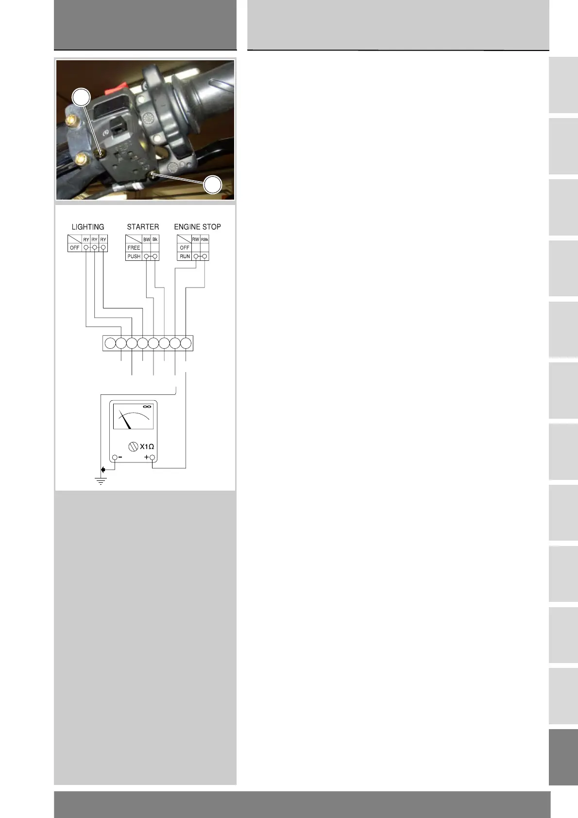
Controllo commutatore
manopola destra
Per rimuovere il commutatore destro
svitare le viti (1) e scollegarlo
dall'impianto elettrico aprendo
la relativa connessione.
I colori citati nelle seguenti descrizioni
si riferiscono ai fili elettrici che escono
dal commutatore e non ai colori dei fili
dell'impianto elettrico principale.
Pulsante engine stop
Con il multimetro verificare le
condizioni di continuità elettrica tra i
cavi (Rosso/Nero e Rosso/Bianco)
(Sez. P 9, relativa al funzionamento
del multimetro). Con il pulsante in
posizione run deve esserci continuità
elettrica tra i due fili. Con pulsante
posizione off non deve esserci
continuità elettrica tra i due fili.
Se queste condizioni non sono
verificate l'interruttore engine stop
non funziona correttamente e deve
essere sostituito. I colori citati si
riferiscono ai fili elettrici che escono
dal commutatore e non ai colori dei fili
dell'impianto elettrico principale.
Pulsante starter
Utilizzando lo stesso procedimento
dell'engine stop, verificare la
continuità elettrica tra i cavi (Blu/
Bianco e Nero), premendo il pulsante
starter (Sez. P 9, relativa al
funzionamento del multimetro). Se le
condizioni di continuità elettrica non
sono verificate il pulsante starter non
funziona e va sostituito. I colori citati
si riferiscono ai fili elettrici che escono
dal commutatore e non ai colori dei fili
dell'impianto elettrico principale.
Deviatore di luce posizione/
anabbagliante
Utilizzando sempre il multimetro
(Sez. P 9, relativa al funzionamento
del multimetro) verificare la continuità
elettrica tra i cavi:
(Rosso/Giallo) per la luce
anabbagliante
Il deviatore luci deve funzionare come
segue:
Collegando il multimetro sui cavi
(Rosso/Giallo) mettendo il deviatore
nella posizione luce anabbagliante,
deve esserci continuità elettrica tra i
due cavi. Se queste condizioni non
sono verificate occorre cambiare il
deviatore delle luci.
Rimontare il commutatore destro
serrando le viti (1) alla coppia
prescritta (Sez. C 3).
Checking the right switch
Undo the screws (1) and disconnect
the right switch from the electric
system to remove it.
Colours mentioned in the
descriptions refer to the colour of
wires from the switch and not to the
colour of wires of the main electric
system.
Engine stop button
Check for continuity between (Red/
Black and Red/White) cables with a
multimeter (Sect. P 9 on multimeter
operation). When the button is in
RUN mode, electric continuity should
be available between the two cables.
When the button is in OFF mode, no
electric continuity should be available
between the two cables.
If the above does not apply, the
ENGINE STOP switch is defective
and should be replaced. Colours
mentioned in the descriptions refer to
the colour of wires from the switch
and not to the colour of wires of the
main electric system.
Starter button
Proceed as described for the engine
stop button and check for continuity
between (Blue/White and Black)
cables when starter button is
pressed (see Sect. P 9 on multimeter
operation). If the above does not
apply, the STARTER button is
defective and should be replaced.
Colours mentioned in the
descriptions refer to the colour of
wires from the switch and not to the
colour of wires of the main electric
system.
Parking light/low beam switch
Using the same multimeter (Sect. P
9, on multimeter operation), check
the continuity across the following
cables:
(Red/Yellow) cables for the low
beam.
The light switch should operate as
follows:
Connect the multimeter to (Red/
Yellow) cables, then position the
switch to low beam mode and
continuity between the two cables
should be available. If the above does
not apply, the light switch should be
replaced.
Fit the right switch, tighten the
screws (1) to the specified torque
(Sect. C 3).
1
1
Y/R Bk V/B
O
Y/B R/O R/G
 Loading...