EasyManua.ls Logo

DUCH CAM888 - User Manual

DUCH CAM888
9 pages
Print Icon
To Next Page IconTo Next Page
Loading...
D CH Users Manual
U
CONTENT
I Preface 1
1.1 Notices when open the cases 2
1.2 Install environment 2
1.3 Warning of installment 3
1.4 Attention of connection design 3
II Function And Specification 4
2.1 Function list 4
2.2 Specification Table 4
III Installation and connection 5
3.1 Installation dimensions 5
3.2 Parts connection diagram 6
3.3 Terminal board description 7
3.4 Interface circuit 8
3.5 Sensor dimension 8
IV System Interface 9
4.1 ATP Function Guide 9
4.2 ATP Action Timing Diagram 10
4.3 Wiring example 10
V Parameter Setting 12
5.1 Key specification 12
5.2 Digital display 12
5.3 Enter setting 12
5.4 Cam parameter setting 13
5.5 System parameter setting 15
5.5.1 System menu entrance 15
5.5.2 System parameter setting table is as following 16
5.5.3 Description of system menus 16
5.5.4 Rotary direction setting
16
5.5.5 Controller 180°calibrate 16
5.5.6 Counts setting 17
5.5.7 Other parameter of controller 17
5.5.8 The production count arriving function 17
VI Protection and alarm 18
6.1 Protection And Alarm Instruction 18
6.2 Protection and trouble codes 18
1
I Preface
Thank you for your using of CAM888 cam controller, here after is called controller, which is
produced by DUCH automatic technology CO., Ltd. The controller adopts the newest
technology. And our company has the completely independent intellectual property. Besides, it is
the national invention patent product. The characteristics are as following:
z Leading technology
It uses the high speed microprocessor, the large-scale field programmable chip and the
entire digital high accuracy high speed control.
Gear change system: Intelligent calculate of stopping at top dead end.
It is dynamic indicating for cam angle setting, which is more human nature.
z High performance
The displayed precision of angle measurement may amount to ±0.1°.
braking test has 2 channels outputs . programmable scissors cam has 6
channels outputs.
Production value has 1channel output.system normal
indication has 1 channel output. Totally 16 channels output.
Before using the controller please read the manual carefully Make sure it is used correctly
and then it will display its high performance. Moreover, this manual is an appendix which is sent
with the controller. Please take care of it after you have used it. So that it will work when you
repair and maintain the controller.
1.1 Notices when open the cases
When open the case, please confirm the following items carefully.
If there is any damage during the delivery.
Check if the rating value on name plate is the same with your requirement. Make sure the
accessories are whole.
Any question please contact us or the supplier.
1.2 Install environment
The height is no more than1000mWhen it is over1000m, it will reduce the capability of
the controller because of the thin air.
Environment temperature -10℃~+40 Environment humidityNo more than 50% at
40. No more than 90% below 20.
When the installation base allowable vibration is 10150HZ, its maximum vibration
acceleration should be no more than 5m/s².
Power supplyDC24V1A.
2
Question and Answer IconNeed help?

Do you have a question about the DUCH CAM888 and is the answer not in the manual?

Summary

I Preface

1.1 Notices when open the cases

Check for damage, rating value, and accessories. Contact supplier if issues arise.

1.2 Install environment

Specifies conditions like altitude, temperature, humidity, and vibration for controller installation.

1.3 Warning of installment

Warns against installing in combustible areas, volatile gases, or extreme environments. Avoid disassembly.

1.4 Attention of connection design

Advises on power source, earthing, filtering, and cable routing for optimal performance and safety.

II Function And Specification

2.1 Function list

Lists controller functions including SPM/Angle display, production value, brake signals, and cam settings.

2.2 Specification Table

Details technical specifications like power supply, operating temperature, angle display, and output channels.

III Installation and connection

3.1 Installation dimensions

Provides outline and hole dimensions for controller mounting.

3.2 Parts connection diagram

Illustrates the wiring connections for sensors, RS485, power supply, and outputs.

3.3 Terminal board description

Details the function and index of each terminal on the controller board.

3.4 Interface circuit

Shows input and output interface circuits for signals and power.

3.5 Sensor dimension

Provides mechanical dimensions for the sensor unit.

IV System Interface

4.1 ATP(Automatic positioning the Top dead end Point) Action Timing Diagram

Illustrates timing diagrams for ATP function in inch, single, and continuous modes.

4.2 ATP(Automatic positioning the Top dead end point) Wiring example

Shows a wiring diagram for connecting the controller to a PLC and other devices.

4.3 ATP Function Guide

Explains how to enable/disable the ATP function and its operating modes.

V Parameter Setting

5.1 Key specification

Describes the function of each key on the controller's operation panel.

5.2 Digital display

Explains the use of the digital monitors for displaying stroke/angle and work count.

5.3 Enter setting

Details the procedure to enter the parameter setting mode using specific key combinations.

5.4 Cam parameter setting

Guides on setting parameters for cutting cam and scissors cam outputs.

5.5 System parameter setting

Explains the importance and password protection for system parameters.

5.5.1 System menu entrance

Details the steps to access the system parameter menu.

5.5.2 System parameter setting table

Lists system parameters like rotary direction and calibration with their settings.

5.5.3 Description of system menus

Clarifies which system parameters are modifiable and which are read-only.

5.5.4 Rotary direction setting

Provides instructions to adjust the controller's rotary direction if it's inconsistent with the mechanical direction.

5.5.5 Controller 180°calibrate

Explains how to calibrate the controller's 180° angle for the rotary transducer.

5.5.6 Counts setting

Describes how to set the counter perspective for work counting.

5.5.7 Other parameter of controller

Covers read-only parameters like electricity times and software edition number.

5.5.8 The production count arriving function

Details the function of F06 for production count reaching and its associated outputs.

VI Protection and alarm

6.1 Protection And Alarm Instruction

Explains how the controller reacts to unusual conditions and displays alarm codes.

6.2 Protection and trouble codes

Lists protection codes, their reasons, and methods to eliminate them.
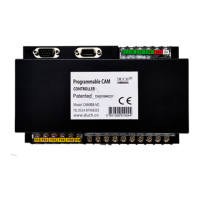
DUCH CAM888 Specifications

General IconGeneral
BrandDUCH
ModelCAM888
CategoryController
LanguageEnglish