D CH Users Manual
U
c. By now the starting angle(oN) in submenu start to flash. Press or to select the
item. Adjust it until the end angle(oF) flashes. Press
to enter the adjustment. Now the
starting angle value at right side will flash. Press or to adjust the parameter. Keep
pressing it for a long time the value will change quickly. When it gets to 90, press
to back to
submenu.
d. At this time the submenu flashes. Press
or to enter the item. Adjust it until the
scissors count (N) flashes. Then press
to enter the adjustment. Now the starting angle value
at right side will flash. Press
or to adjust the parameter. Keep pressing it for a long time
the value will change quickly. When it gets to 15, press to back to submenu.
e. Under the submenu, press
to back to the main menu. Press the key once more it will
exit the setting process. At last the system will save the data automatically. The setting is over.
Remind: When you adjust the starting angle the circumferential 36 indicating lamp will
display the cam range which you want to adjust. It is more intuitionistic.
5.4.2 Production count reaches prarameter setting
a. In the system menu FC is production count item .
b. Input the FC setting menu, press
change the value ,and then press and
regulation of the value. After setting ,press to exit the setting. System saves the data
automatically.
5.5 System parameter setting
The system parameter is important for controller work. Do not change it unless the system
needs to be debugged. The system parameter is equipped with the password protection.
5.5.1 System menu entrance
a.
When the device is in idle condition,press and together for more than 3
15
seconds to make the controller enters into setting status.
b. Now the quaternion digital monitor upside will flash. Press
or to select the
menu. Choose P01 and press to enter it.
c. Input the system password by
or . Press to return to the main menu.
d. Press or to select the menu. Item P02-P12 will appear.
Caution: password = 777.
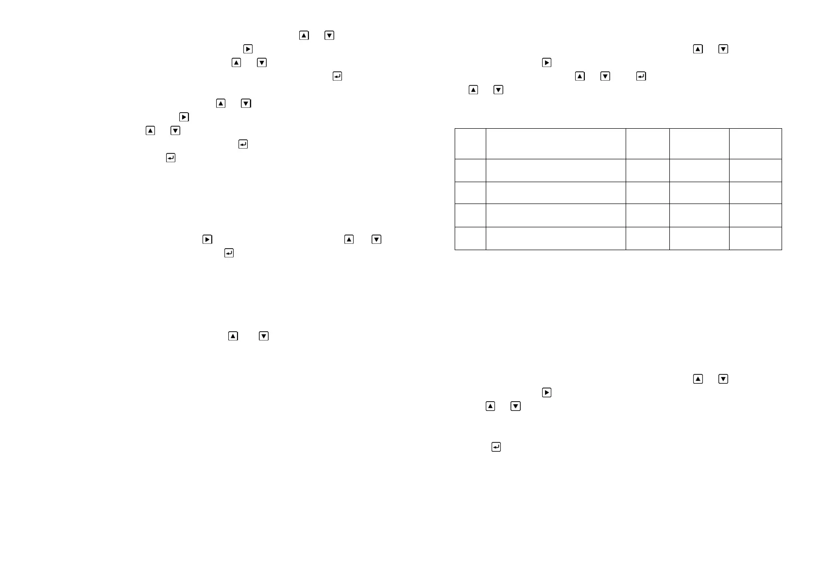
5.5.2 System parameter setting table is as following:
5.5.3 Description of system menus:
In the system menu P02-P03 is modifiable parameter item while P11-P12 is read-only
item. The settable parameter item is used to set the parameter or system state. The read-only
item is merely used to observe the related parameter of the controller.
5.5.4 Rotary direction setting
When install the controller, if you find that the crank rotary direction is inconsistent from
the controller indicating direction please reset the direction value in menu P02.
The method is as following:
a. Use the same steps as 5.5.1 to enter the system menu
b. Now the quaternion digital monitor upside will flash. Press
or to select the
menu. Choose P02 and press
to enter it.
c. Use or to select 0 or 1.Attention: if you find that the crank rotary direction is
inconsistent from the controller indicating direction please select 0 while the original value is 1
and select 1 while it is 0.
d. Press
to back to the main menu. Press the key once more it will exit the setting
process. At last the system will save the data automatically. The setting is over.
5.5.5 Controller 180°calibrate
It adopts absolute value rotary transducer. Because the mounting position of transducer
does not correspond to crank shaft position completely, they need to be calibrated. The angle is
180°.
16
Cod
e
Description Unit Range Default
P02 Rotary direction setting 0~1 0
P03 180°calibration 0~359
P11 Electricity times on controller Read-only
P12 Controller software edition number Read-only