D CH Users Manual
U
3.3 Terminal board description:
7
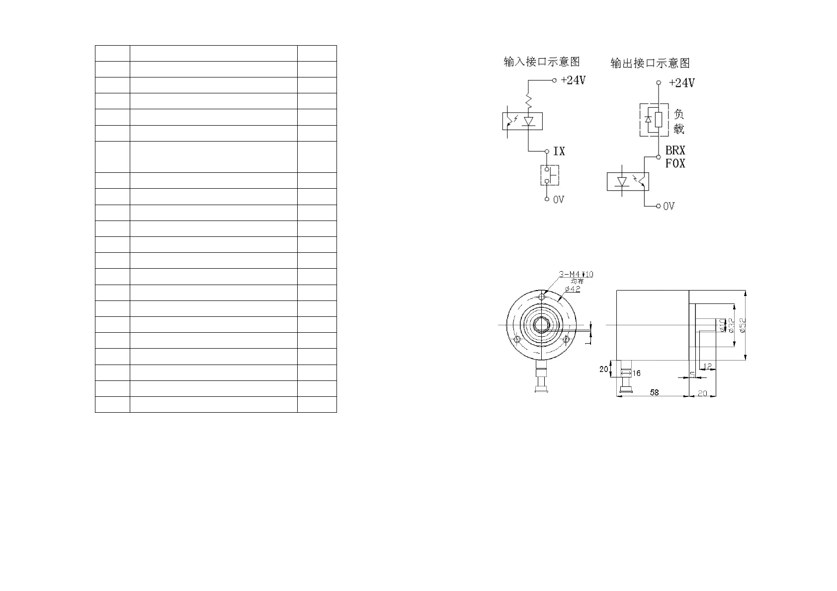
3.4 Interface circuit
3.5 Sensor dimension
8
NO Name Index
F01 Cutting cam output 1
F02 Cutting cam output 2
F03 Cutting cam output 3
F04 Cutting cam output 4
F05 Cutting cam output 5
F06 Cutting cam output (production count
reaches output)
6
F07 Cam output 7
F08 Cam output 8
F09 Cam output 9
F10 Cam output 10
F11 Cam output 11
F12 Cam output 12
FC Production value output 13
RD Normal Indication Signal System 14
BR1 Brake signal 1 15
BR2 Brake signal 2 16
24V
+24V power supply terminal
18
0V 0V power supply terminal 19
I1 System reset 20
I2 ATP 21
I3 Running 22