Service Manual for Subway Front Counters
10
NOTICE: Using a Refrigeration-Charging Unit,
evacuate refrigerant from the system according
to Duke Manufacturing Service Bulletin Number
26. Refrigerant must be recovered in accordance
with Federal, State and Local regulations.
3. Removal of the Lower Shelf if necessary to pull
the Condensing unit out from under the unit.
4. Remove the insulation from the Suction Line at
the Compressor. Be careful, as the Accumulator
Insulation will be reused.
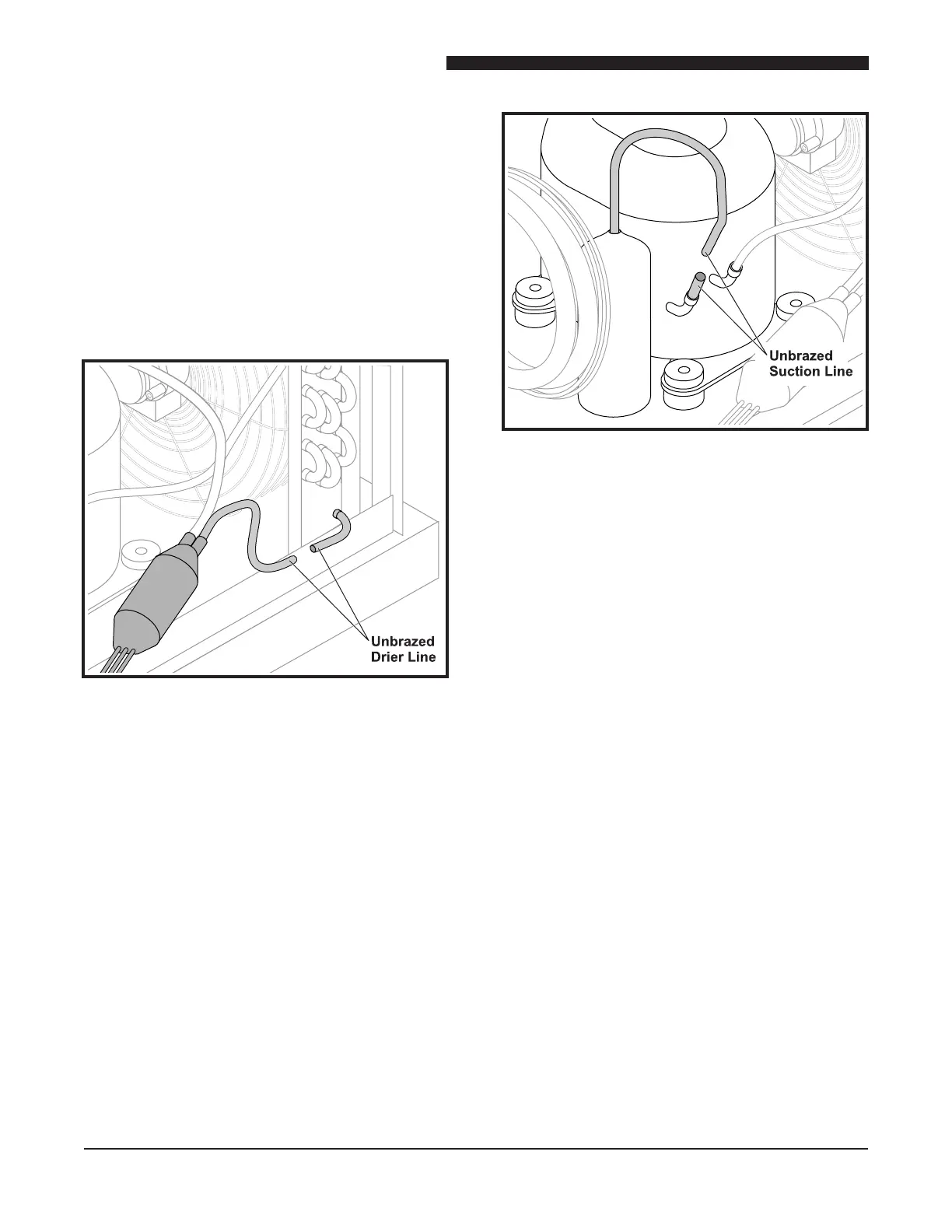
Un-brazed Drier – Condenser Side
NOTICE: Note the position of the Drier; the new
Drier must be installed in the same position. See
the illustration above.
5. Un-braze the Drier from the Condenser Outlet,
see the illustration above.
Un-brazed Suction Line
6. Un-braze the Suction Line from the Compressor,
see the illustration above.
NOTICE: Care should be given to support the
Condensing unit once out of the cage.
7. Slide the Condensing unit out of the cage as
far as possible.
8. Remove the insulation from each of the
Evaporator Inlets and the Suction Line at the
Manifold.
9. Cut each Evaporator Inlet Tube 1″ from the end
of the Capillary Tube. Cut the Suction Line 4″
from the Manifold.
10. Install the new Capillary Tube Assembly onto
Condensing unit.
CAUTION: A heat sink must be used
when brazing the suction line
at the manifold to ensure that
the thermostat bulb does not
overheat.
11. Reinstall the Condensing unit; braze the
Suction Line to the Compressor and the Drier
connection to the Condenser Outlet.
12. Leak check the system.
13. Re-insulate the Evaporator Inlets, Suction Line
and Accumulator.