Makevisualcheckof mainburnerandpilotflamesatstart
ofheatingseasonandagaininmid-season.Mainburner
flameshouldhavewelldefinedinnerbluemantelwith
lighterblueoutermantel.Checkburnerthroatsandburner
orificesforlintor dustobstruction.SeeFigures17and 19.
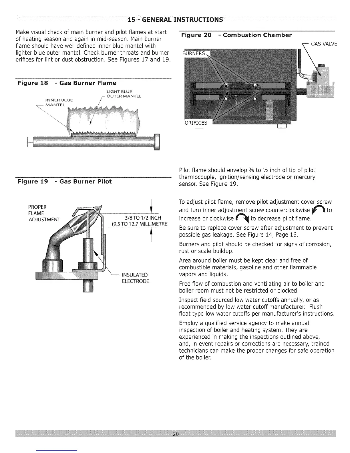
Figure 20
BURNERS,
- Combustion Chamber
GAS VALVE
ORIFICES
Figure 19 - Gas Burner Pilot
Pilot flame should envelop 3/8to 1/2inch of tip of pilot
thermocouple, ignition/sensing electrode or mercury
sensor. See Figure 19.
PROPER
FLAME
ADJUSTMENT
3/8TO1/2 iNCH
(95 TO 1Z7 MILUMETRE
t
iNSULATED
ELECTRODE
To adjust pilot flame, remove pilot adjustment cover screw
and turn inner adjustment screw counterclockwise _ to
ir
increase or clockwise _ to decrease pilot flame.
Be sure to replace cover screw after adjustment to prevent
possible gas leakage. See Figure 14, Page 16.
Burners and pilot should be checked for signs of corrosion,
rust or scale buildup.
Area around boiler must be kept clear and free of
combustible materials, gasoline and other flammable
vapors and liquids.
Free flow of combustion and ventilating air to boiler and
boiler room must not be restricted or blocked.
Inspect field sourced low water cutoffs annually, or as
recommended by low water cutoff manufacturer. Flush
float type low water cutoffs per manufacturer's instructions.
Employ a qualified service agency to make annual
inspection of boiler and heating system. They are
experienced in making the inspections outlined above,
and, in event repairs or corrections are necessary, trained
technicians can make the proper changes for safe operation
of the boiler.