6 = SUPPLY AND RETURN PIPING ...........................
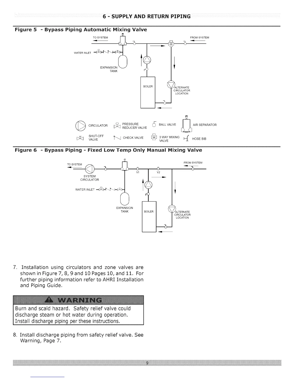
Figure 5
Figure 6
- Bypass Piping Automatic Mixing Valve
TO SYSTEM
WATER INLET
EXPANSION
TANK
z
FROM SYSTEM
_\ iii
_ER "_ JALTERNATE
CIRCULATOR
LOCATION
(_ C,ROOLATOR_ P"ESSUREREoUOERVALVE_ BAL'VA'VE01A'RSEPARATORE::
VA_vESRO_OFFt'q CHECKVALVE_ VA_vESWAYMIX'NG_ HOSEBIB
- Bypass Piping - Fixed Low Temp Only Manual Mixing Valve
TO SYSTEM S_
CIRCULATOR 0 .......
WATER INLET
EXPANSION
TANK
©
V2
FROM SYSTEM
i5--
_,,,,')
ER _- _JALTERNATE
CIRCULATOR
LOCATION
.
Installation using circulators and zone valves are
shown in Figure 7, 8, 9 and 10 Pages 10, and 11. For
further piping information refer to AHRI Installation
and Piping Guide.
Burn and scald hazard. Safety relief valve could
discharge steam or hot water during operation.
Install discharge piping per these instructions.
8. Install discharge piping from safety relief valve. See
Warning, Page 7.